
Audio signal conversion device and method

A technology of audio signal and conversion device, which is applied in the field of signal processing and can solve the problem of single perception mode of the deaf-mute

Pending Publication Date: 2018-04-06
刘宏波
View PDF0 Cites 0 Cited by
  • Summary
  • Abstract
  • Description
  • Claims
  • Application Information

AI Technical Summary

Problems solved by technology

But only through sign language, the perception mode of the deaf-mute is undoubtedly single, making it impossible for many deaf-mute people to form a better perception experience of social forms from the perspective of multi-modal perception

Method used


Image

  • Audio signal conversion device and method
  • Audio signal conversion device and method
  • Audio signal conversion device and method

Examples


no. 1 example

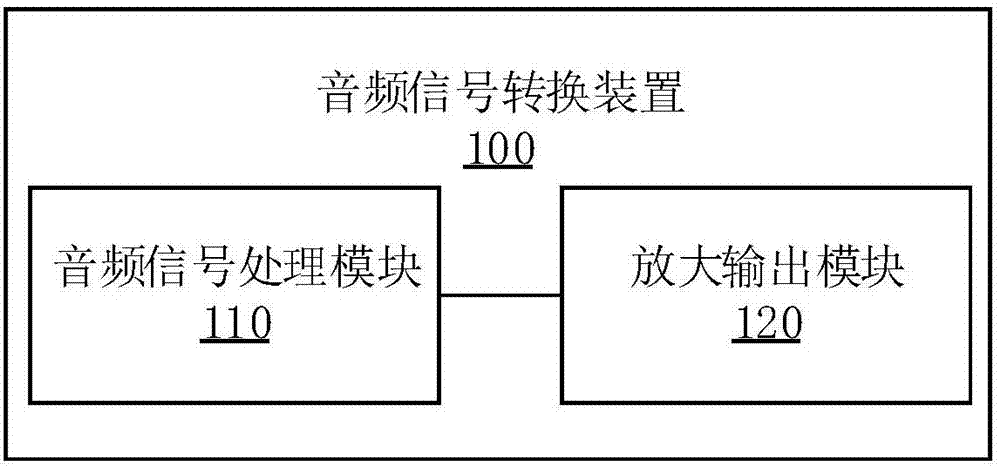
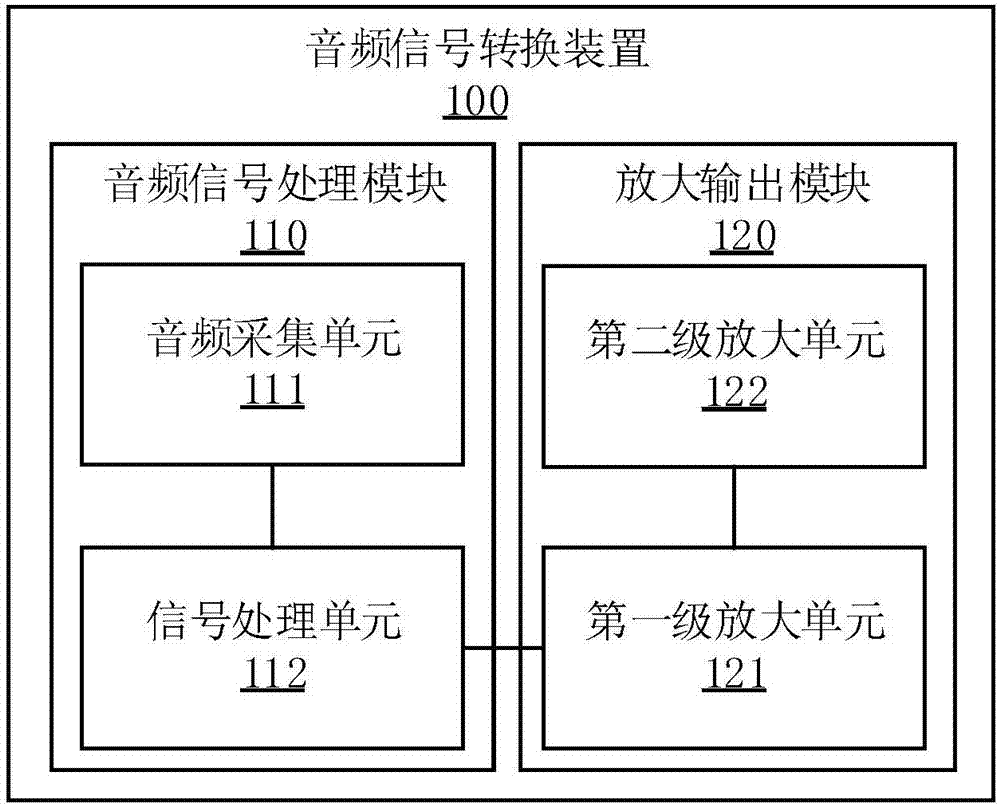
[0033] see figure 1 , the first embodiment of the present invention provides an audio signal conversion device 100 , the audio signal conversion device 100 includes: an audio collection and processing module 110 and an amplification and output module 120 . Wherein, the audio collection and processing module 110 is connected to the amplifying output module 120, and the output end of the amplifying output module 120 can be used to contact the user's skin, and the user can also be a deaf-mute person.

[0034] The audio collection and processing module 110 is used for collecting audio signals, and judging whether a preset audio signal matches the collected audio signals. When the judgment is yes, generate a characteristic waveform signal corresponding to the audio signal to the amplifying and outputting module 120 .

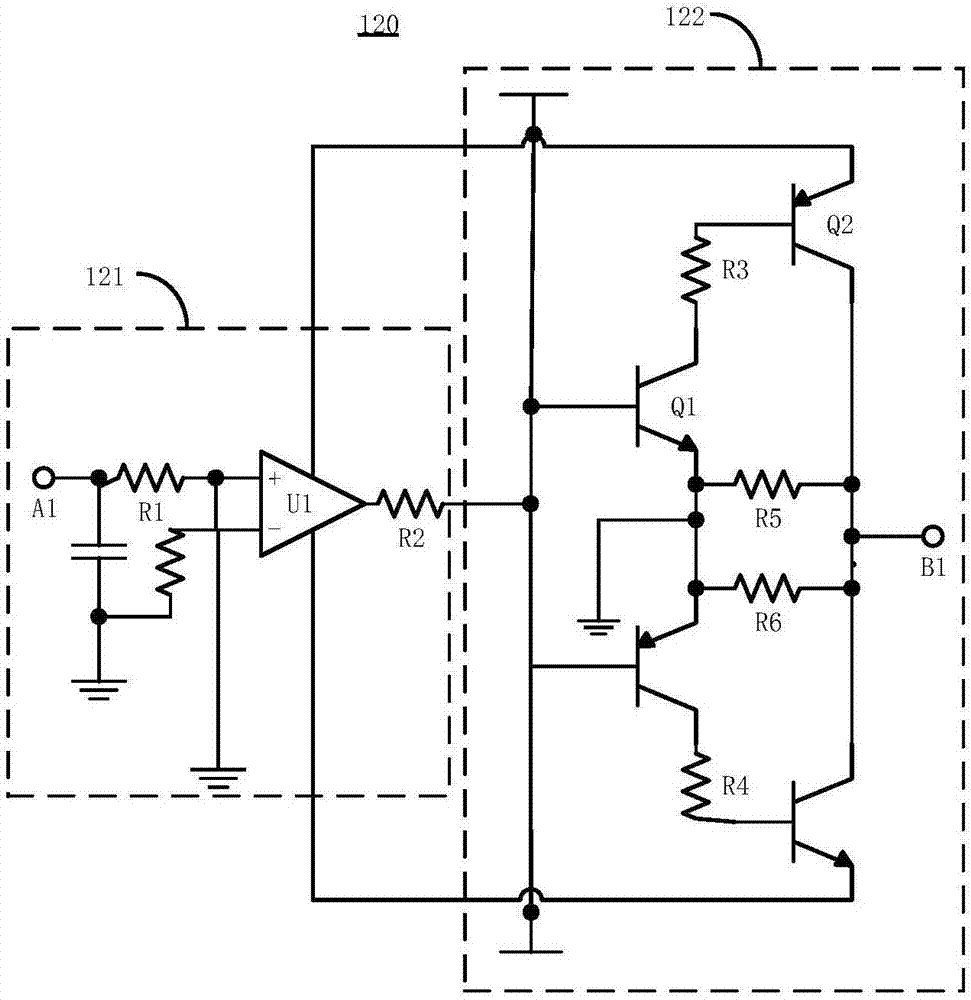
[0035] The amplifying output module 120 is used to amplify the current value of the characteristic waveform signal to obtain the amplified characteristic waveform s...

no. 2 example

[0055] see Figure 5 , the second embodiment of the present invention provides an audio signal conversion method applied to an audio collection and processing module of an audio signal conversion device. The audio signal conversion method includes: step S100 and step S200.

[0056] Step S100: Determine whether a preset audio signal matches the collected audio signal.

[0057] Step S200: If yes, generate a characteristic waveform signal corresponding to the audio signal to the amplifying and outputting module.

[0058] see Image 6 , in an audio signal conversion method provided in the second embodiment of the present invention. The method sub-flow of step S100 includes: step S110 and step S120.

[0059] Step S110: converting the obtained audio signal into a corresponding audio feature sequence.

[0060] Step S120: converting the obtained audio signal into a corresponding audio feature sequence.

[0061] It should be noted that, as those skilled in the art can clearly und...


PUM

PropertyMeasurementUnit
Electric currentaaaaaaaaaa

Abstract

The embodiment of the invention provides an audio signal conversion device and method, and relates to the technical field of signal processing. The device comprises an audio acquisition and processingmodule and an amplification and output module; the amplification and output module is connected with the audio acquisition and processing module; the output end of the amplification and output moduleis used for being contacted with the skin of a user; the audio acquisition and processing module is used for judging whether a pre-set audio signal is matched with an acquired audio signal or not, and if so, generating a characteristic waveform signal having the corresponding relationship with the audio signal to the amplification and output module; and the amplification and output module is usedfor amplifying the current value of the characteristic waveform signal to obtain the amplified characteristic waveform signal, and outputting the amplified characteristic waveform signal through an output end. The amplified characteristic waveform signal can generate the electrical sensation corresponding to the waveform of the characteristic waveform signal at the skin contact position of the user; therefore, due to the audio acquisition and processing module, the user can realize audio perception through touch; and thus, the user has better perception experience on social formation.

Description

technical field [0001] The present invention relates to the technical field of signal processing, in particular to an audio signal conversion device and method. Background technique [0002] Deaf-blind people have difficulty perceiving social forms through speaking and hearing because they themselves cannot hear and speak. [0003] At present, many deaf-mute people use sign language to communicate with other deaf-mute people or normal people, so that many deaf-mute people can form a perception of social forms through sign language. However, only through sign language, the perception mode of the deaf-mute is single, making it impossible for many deaf-mute people to form a better perception experience of social forms from the perspective of multi-modal perception. [0004] Therefore, how to enable the deaf-mute to form a better perception experience of social forms is currently a major problem in the industry. Contents of the invention [0005] In view of this, the purpose...

Claims


Application Information

Patent Timeline
IPC IPC(8): H04R3/00
CPCH04R3/00H04R2430/00
Inventor 刘宏波
Owner 刘宏波
Learn More