
Solid-stage fertilizer application apparatus

A fertilization device and fertilizer technology, which are applied to fertilization devices, fertilizer distributors, grain processing and other directions, can solve the problems of poor control of the amount of fertilization, unfavorable mechanical fertilization, and inconvenient operation, so as to improve the overall efficiency and the automatic control rate, The effect of improving the efficiency of fertilization and improving the uniformity of crushing

Inactive Publication Date: 2018-04-10
韦健敏
View PDF9 Cites 0 Cited by
  • Summary
  • Abstract
  • Description
  • Claims
  • Application Information

AI Technical Summary

Problems solved by technology

[0002] At present, in the field of agriculture, after sowing, agricultural workers often need to apply fertilizers in order to promote the germination of seeds. When fertilizing, they generally put the fertilizers in the fertilizer buckets, and then manually lift the fertilizer buckets to the farmland, and then Apply fertilizer to the sowing place, but this method is time-consuming and labor-intensive, and the amount of application is not easy to control, and the fertilization efficiency is not high; in addition, during the production, processing, storage and transportation of solid granular fertilizers, caking problems often occur , which brings many difficulties to storage, transportation and use. Serious agglomeration of chemical fertilizers is difficult to break. Partial agglomeration of chemical fertilizers is not good for mechanical fertilization, and it is easy to block the nozzle. These will bring inconvenience to fertilization, and fertilizers can be used only after crushing Plants fully absorb the fertilizer fertility, the existing fertilizer applicator has poor crushing effect, inconvenient operation, time-consuming and laborious use, and poor fertilization effect

Method used


Image

  • Solid-stage fertilizer application apparatus
  • Solid-stage fertilizer application apparatus
  • Solid-stage fertilizer application apparatus

Examples


Embodiment Construction

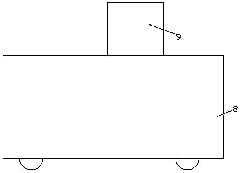
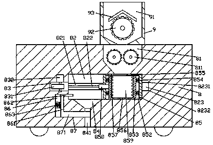
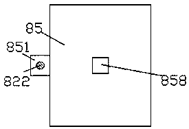
[0019] Such as Figure 1-Figure 4 As shown, a fertilization device for solid fertilizer of the present invention includes a fertilization car body 8 and a feeding box 9 installed on the top of the fertilization car body 8, and a feeding chamber 91 is provided in the feeding box 9, and the feeding chamber 91 is provided with a first rotating crushing part 92, and the fertilization car body 8 at the bottom of the feeding box 9 is provided with a crushing chamber 81 whose top communicates with the bottom of the feeding chamber 91. The crushing chamber 81 is provided with There is a second rotating crushing part 811 symmetrically arranged left and right. The fertilization car body 8 at the bottom of the crushing chamber 81 is connected with a sliding chamber 82 extending to the left. The rear inner wall of the sliding chamber 82 is provided with a There is a guide groove 821, and a threaded rod 822 extends left and right in the guide groove 821. The left end of the threaded rod 82...


PUM


Abstract

The invention discloses a solid-state fertilizer application apparatus, which comprises a fertilizer application vehicle body and a material feeding box arranged on the top portion of the fertilizer application vehicle body, wherein a material feeding cavity is arranged in the material feeding box, a first rotation breaking member is arranged in the material feeding cavity, a breaking cavity withthe top portion communicated to the bottom portion of the material feeding cavity is arranged in the fertilizer application vehicle body on the bottom portion of the material feeding box, second rotation breaking members symmetrically arranged left and right are arranged in the breaking cavity, a sliding cavity capable of extending toward the left side is communicated in the fertilizer applicationvehicle body on the bottom portion of the breaking cavity, a guide groove is arranged in the rear side inner wall of the sliding cavity, a threaded rod capable of extending left and right is arrangedin the guide groove, the threaded rod left side extending end is rotatably connected to the left side inner wall of the guide groove in a matched manner, the threaded rod right side extending end isconnected to a first motor in a matched manner, the outer surface of the first motor is embedded in and fixedly connected to the right side inner wall of the guide groove, and a sliding box is slidably connected in the sliding cavity in a matched manner. According to the present invention, the solid-state fertilizer application apparatus has advantages of simple structure, convenient operation, high safety, breaking quality improving, fertilizer application effect improving and operator labor reducing.

Description

technical field [0001] The invention relates to the technical field of agricultural machinery, in particular to a fertilization device for solid fertilizer. Background technique [0002] At present, in the field of agriculture, after sowing, agricultural workers often need to apply fertilizers in order to promote the germination of seeds. When fertilizing, they generally put the fertilizers in the fertilizer buckets, and then manually lift the fertilizer buckets to the farmland, and then Apply fertilizer to the sowing place, but this method is time-consuming and labor-intensive, and the amount of application is not easy to control, and the fertilization efficiency is not high; in addition, during the production, processing, storage and transportation of solid granular fertilizers, caking problems often occur , which brings many difficulties to storage, transportation and use. Serious agglomeration of chemical fertilizers is difficult to break. Partial agglomeration of chemic...

Claims


Application Information

Patent Timeline
IPC IPC(8): B02C4/08B02C4/10B02C19/00B02C23/16A01C15/12
CPCB02C4/08A01C15/12B02C4/10B02C19/00B02C23/16B02C2023/165
Inventor 韦健敏
Owner 韦健敏
Learn More