Road curvature based self-adaption vehicle speed adjustment system and method

An adaptive adjustment, road curvature technology, applied in the field of auto driving, can solve problems such as traffic accidents, driver discomfort, vehicles running out of lanes, etc., to improve safety and comfort, improve comfort, and avoid car accidents. dangerous effect

Inactive Publication Date: 2018-04-10
CHONGQING CHANGAN AUTOMOBILE CO LTD
View PDF10 Cites 21 Cited by
  • Summary
  • Abstract
  • Description
  • Claims
  • Application Information

AI Technical Summary

Problems solved by technology

[0002] The current automatic control of vehicle speed basically follows the control mode of adaptive cruise technology (hereinafter referred to as ACC), that is, the speed control strategy is that if there is no target vehicle ahead, cruise at the set speed; After keeping the set safety distance, it will automatically accelerate or decelerate following the target car identified in front. For the situation that there is a curve ahead, there are currently some control strategies, mainly relying on the vehicle's own yaw angle signal, corner signal, etc., to realize the vehicle Decelerate after entering the curve to achieve the vehicle speed comfort control target, but these strategies cannot realize the deceleration before the vehicle enters the curve. Therefore, the traditional speed control strategy cannot adaptively decelerate before entering the curve. When driving at a high speed and there is no target car in front, the vehicle will maintain the set speed and enter the curve. If the set speed is too high at this time, it will cause discomfort to the driver. If it is a sharp curve, the vehicle may even appear Risk of running out of lane, causing traffic accident

Method used


Image

  • Road curvature based self-adaption vehicle speed adjustment system and method
  • Road curvature based self-adaption vehicle speed adjustment system and method
  • Road curvature based self-adaption vehicle speed adjustment system and method

Examples


Embodiment Construction

[0027] The present invention will be further described below in conjunction with accompanying drawing.

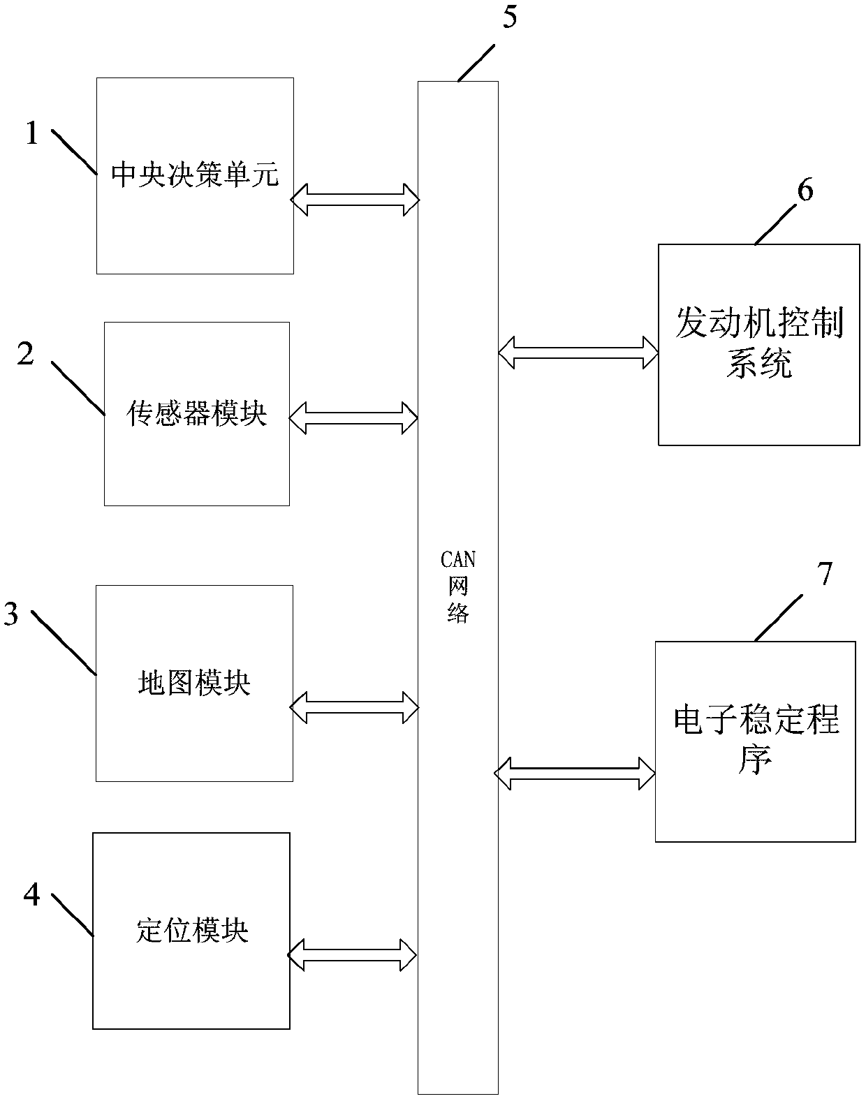
[0028] Such as figure 1 The shown system for adaptively adjusting vehicle speed based on road curvature includes sensor module 2, map module 3, positioning module 4, CAN network 5, central decision-making unit 1, engine control system 6 and electronic stability program 7, sensor module 2, map The module 3, the positioning module 4, the CAN network 5, the central decision-making unit 1, the engine control system 6 and the electronic stability program 7 communicate through the CAN network. in:

[0029] Sensor module 2, which includes radar and camera), is used to identify the vehicle ahead, lane line and obstacle information.

[0030] The map module 3 is used to provide lane curvature information. In this embodiment, the map module 3 uses a high-precision map.

[0031] The positioning module 4 is used to calculate the current location information of the vehicle. In this em...


PUM


Abstract

The invention discloses a road curvature based self-adaption vehicle speed adjustment system and method. The road curvature based self-adaption vehicle speed adjustment system includes a sensor module, a map module, a positioning module, a CAN network, a central decision-making unit, an engine control system and an electronic stable program; the central decision-making unit calculates a target control speed Vm under a lane radius while determining that a curve having the lane radius R less than or equal to RF exists in an M-meter range on the front of a vehicle according to information recognized by the sensor module and information provided by the map module and the positioning module, compares the target control speed Vm and a speed Vacc calculated by a self-adaption cruise system in theworking condition, and takes a minimum value of the Vm and the Vacc as a final target control speed Vf; and the central decision-making unit sends a deceleration control command according to the final target control speed Vf, and performs deceleration control. The road curvature based self-adaption vehicle speed adjustment system and method start deceleration before the vehicle enters the curve,and can ensure the safety and the comfort of driving.

Description

technical field [0001] The invention belongs to automobile automatic driving technology, and in particular relates to a system and method for adaptively adjusting vehicle speed based on road curvature. Background technique [0002] The current automatic control of vehicle speed basically follows the control mode of adaptive cruise technology (hereinafter referred to as ACC), that is, the speed control strategy is that if there is no target vehicle ahead, cruise at the set speed; After keeping the set safety distance, it will automatically accelerate or decelerate following the target car identified in front. For the situation that there is a curve ahead, there are currently some control strategies, mainly relying on the vehicle's own yaw angle signal, corner signal, etc., to realize the vehicle Decelerate after entering the curve to achieve the vehicle speed comfort control target, but these strategies cannot realize the deceleration before the vehicle enters the curve. Ther...

Claims


Application Information

Patent Timeline
Patent Type & Authority Applications(China)
IPC IPC(8): B60W30/02B60W30/045B60W10/06B60W30/14
CPCB60W30/025B60W10/06B60W30/045B60W30/143
Inventor 文滔丁可孔周维
Owner CHONGQING CHANGAN AUTOMOBILE CO LTD
Why Eureka
Try Eureka