
A Small Rotation Angle Pantograph Bow Head Balance Mechanism

A technology of balancing mechanism and pantograph, applied in the field of pantograph, can solve the problems affecting the current receiving quality of the pantograph, and achieve the effects of improving the current receiving quality, reducing the damage of pantograph and catenary, and reducing the deflection angle.

Active Publication Date: 2020-11-27
ZHUZHOU ELECTRIC LOCOMOTIVE CO LTD
View PDF5 Cites 0 Cited by
  • Summary
  • Abstract
  • Description
  • Claims
  • Application Information

AI Technical Summary

Problems solved by technology

This will seriously affect the current quality of the pantograph

Method used


Image

  • A Small Rotation Angle Pantograph Bow Head Balance Mechanism
  • A Small Rotation Angle Pantograph Bow Head Balance Mechanism
  • A Small Rotation Angle Pantograph Bow Head Balance Mechanism

Examples


Embodiment Construction

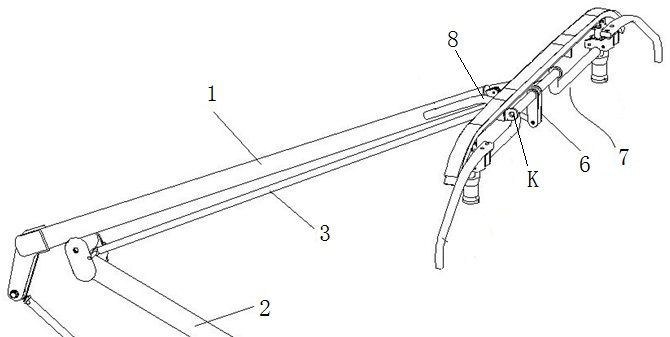
[0033] Such as Figure 4~6 As shown, a pantograph head balance mechanism with a small rotation angle includes a balance bar system, the balance bar system includes a first bar 3 hinged to the upper end of the lower arm 2, a second bar 4 hinged to the upper end of the upper arm 1, The fourth rod 6 fixedly connected to the middle position of the bow shaft 7, the third rod 5 whose one end is hinged with the free end of the second rod 4 and whose other end is hinged with the free end of the fourth rod 6 .

[0034] The first rod 3 is arranged directly below the upper arm rod 1 , and the other end of the first rod 3 is hinged to the middle part of the second rod 4 . The upper end of the upper arm 1 is extended with a connecting portion 8 , and the connecting portion 8 is hinged to the bow head rotating shaft 7 . The second rod 4 is an arc rod, and its bending direction faces the first rod 3 .

[0035] The bow head rotating shaft 7 has a π-shaped structure, including a hollow middl...


PUM


Abstract

The invention discloses a pantograph bow balancing mechanism for a small-deflection-angle pantograph. The pantograph bow balancing mechanism comprise a balancing rod system which comprises a first rodhinged to the upper end of a lower arm rod, a second rod hinged to the upper end of an upper arm rod, a fourth rod fixedly connected with the middle of a pantograph bow rotary shaft, and a third rodwith one end being hinged to the free end of the second rod and the other end being hinged to the free end of the fourth rod. The other end of the first rod is hinged to the middle of the second rod,and the upper end of the upper arm rod is provided with a connecting part in an extending mode. The connecting part is hinged to the pantograph bow rotary shaft, and the second rod is in an arc shapeand bends towards the first rod. According to the pantograph bow balancing mechanism, through changing of the relative positions of rotating hinges of all rod pieces of a pantograph balancing system,the deflection angle of a pantograph bow is remarkably decreased, thus the contact area of the pantograph and a rigid catenary is increased, the current collecting quality of the pantograph is effectively improved, and pantograph-catenary damage is reduced.

Description

technical field [0001] The invention belongs to the technology of pantographs, and in particular relates to a pantograph head balance mechanism with a small rotation angle. Background technique [0002] When the single-carbon slide plate pantograph is in contact with the catenary to receive current, the contact area is easily affected by the deflection angle of the bow head caused by the dynamic movement of the balance mechanism of the pantograph head and the vertical line perpendicular to the longitudinal neutral plane of the track. influences. When the deflection angle of the bow head is large, the contact between the single carbon slide plate and the rigid catenary changes from a line contact to a point contact, so that the quality of the current receiving drops sharply, and it is easy to burn the carbon slide plate and the catenary. [0003] According to the requirements of the Chinese standard EMU for the 350km / h high-speed pantograph, the bow head balance mechanism is...

Claims


Application Information

Patent Timeline
Patent Type & Authority Patents(China)
IPC IPC(8): B60L5/22
CPCB60L5/22
Inventor 王先锋袁文辉张彦林蒋忠城冯叶陈敏坚
Owner ZHUZHOU ELECTRIC LOCOMOTIVE CO LTD
Learn More