Wearable AR system, AR display device and its projection source module

a technology of display device and wearable ar, which is applied in the field of wearable ar system, ar display device and its projection source module, can solve the problems of limited system limit resolution, difficult to increase the number of apertures, and more stray ligh

Active Publication Date: 2022-11-15
MATRIXED REALITY TECH CO LTD
View PDF63 Cites 2 Cited by
  • Summary
  • Abstract
  • Description
  • Claims
  • Application Information

AI Technical Summary

Benefits of technology

[0008]An object of the present application is to solve at least one of the above drawbacks, to provide a novel projection source module in which a gap between a projection source and a beam shaping element is eliminated, and to provide an AR display device comprising the novel projection source module as well as a wearable AR system comprising the AR display device.
[0009]Specifically, according to one aspect, an augmented reality display device is provided which comprises a projection source module and an optical path module, the projection source module comprising a projection source and a beam shaping element which are integrated into a unitary piece, and the optical path module comprising a beamsplitter and a reflector, wherein virtual image light emitted from the projection source and carrying virtual image information is emitted out of the projection source module after being shaped by the beam shaping element, projected onto the beamsplitter first, then reflected onto the reflector by the beamsplitter, then reflected by the reflector, and enters a human eye eventually, and scene light carrying real scene information enters the reflector from an outside of the reflector, and is transmitted through the reflector and the beamsplitter into the human eye. The fact that the projection source and the beam shaping element of the projection source module are closely bonded reduces a refractive index difference at an interface of a lens forming the beam shaping element, improves a transmittance of rim light, reduces ghost images, and enhances brightness of an image.
[0010]In a feasible embodiment, the beam shaping element is integrated directly to the projection source, and for example, the beam shaping element is adhesively bonded to the projection source in a face-fitting manner. In cases that the projection source and the beam shaping element have complementary contact surfaces that can be face-fitted to each other, they can be directly bonded and integrated together. The above object is achieved, and the number of components is minimized and the formed structure is simpler and more compact.
[0025]In the projection source module, the augmented reality display device and the wearable augmented reality system, the projection source providing virtual image information and the beam shaping element for shaping the light from the projection source are bonded directly and tightly or integrated into the unitary piece via the intermediate matching member. The virtual image light from the projection source enters the lens forming the beam shaping element without passing through air, as a result of which, the refractive index difference at the interface of the lens is decreased, a light transmittance is improved, a light efficiency is improved, and generation of stray light and ghost images is suppressed. By increasing the refractive index of an image space, a relatively larger numerical aperture can be achieved with a relatively smaller aperture angle, a deflection angle of rim light is decreased, and design is simplified. The application can also provide at least one of the advantages that the formed optical system is more compact, smaller in size, lighter in weight, easy to assemble and adjust, high in system strength, and comfortable to wear.

Problems solved by technology

Due to a low refractive index of the air, a numerical aperture is difficult to increase, and a limit resolution of a system is limited.
Due to a large refractive index difference at an interface of the lens 2 with the air, i.e. at an incident surface of the light, relatively more light is reflected at the interface, generating more stray light and resulting in serious ghost phenomenon.
Meanwhile, the projection source 1 and the lens 2 are discrete and separate components, and thus the optical structure is large in size, difficult to assemble and adjust, and easily damaged.

Method used


Image

  • Wearable AR system, AR display device and its projection source module
  • Wearable AR system, AR display device and its projection source module
  • Wearable AR system, AR display device and its projection source module

Examples


first embodiment

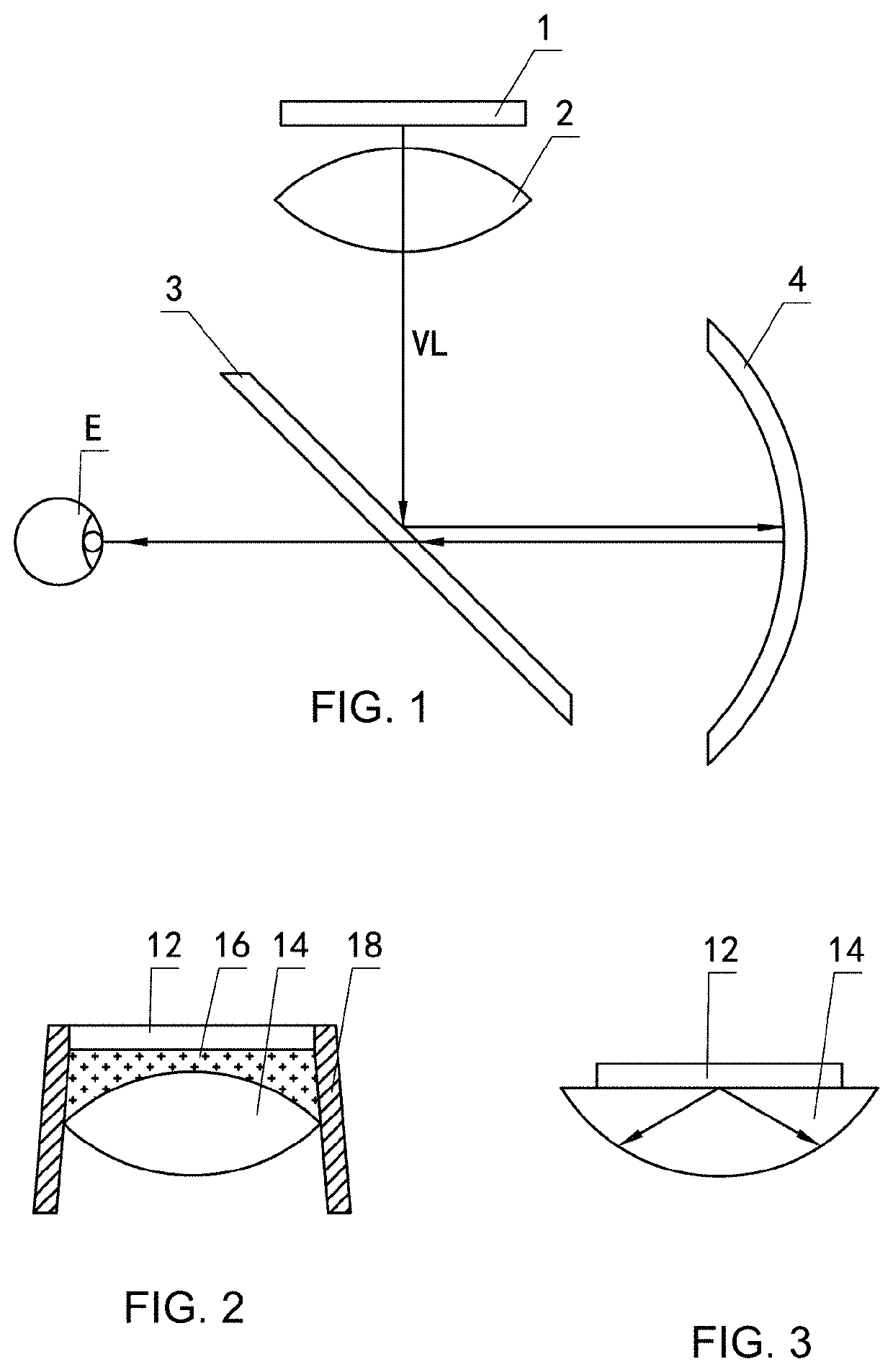
[0040]FIG. 2 shows a projection source module of an AR display device according to the present application. In this embodiment, a projection source 12 and a beam shaping element 14 are integrated together indirectly via an intermediate matching member 16. In this embodiment, the beam shaping element 14 is provided as a lens, the intermediate matching member 16 is formed from a liquid medium and / or a liquid crystal medium, and accordingly, the projection source module comprises a sealing structure for sealing the liquid medium or the liquid crystal medium between the projection source 12 and the beam shaping element 14. The sealing structure can be any suitable sealing structure in the art.

[0041]In a feasible embodiment, the sealing structure comprises a sealing frame 18, the sealing frame 18 being sealed to the projection source 12 by adhesive bonding and the sealing frame 18 being sealed to the lens forming the beam shaping element 14 by an embedding engagement. Alternatively, depe...

second embodiment

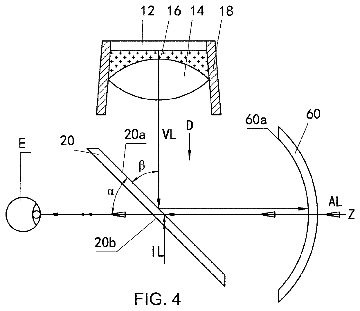
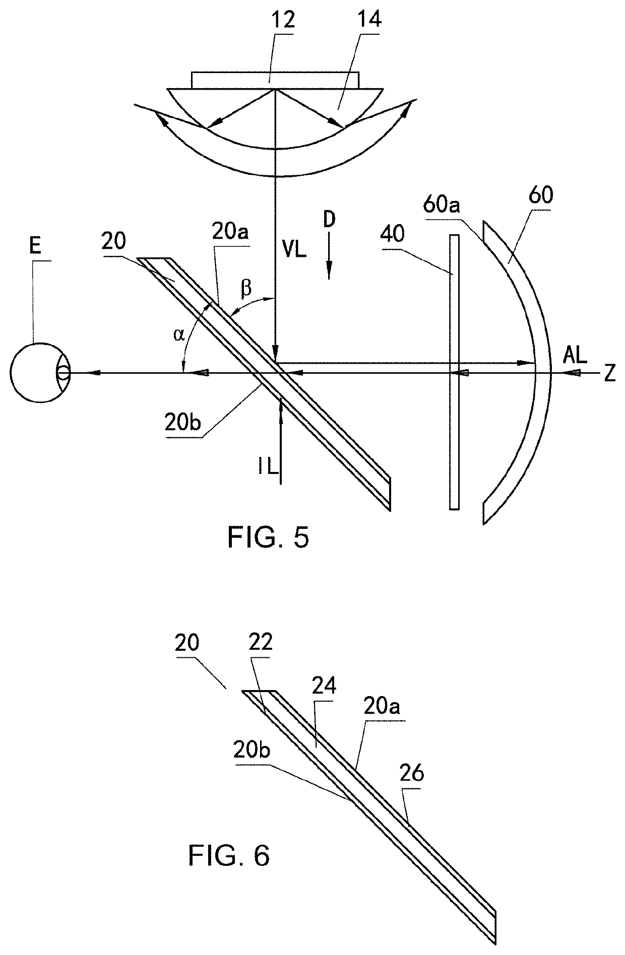
[0053]However, in the present configuration, there is also interference light IL (indicated by double solid arrows in FIGS. 4 and 5) which is incident on the beamsplitter 20 from a side of the beamsplitter 20 which is opposite to an incident side from which the virtual image light VL is incident on the beamsplitting side 20a. A portion of the interference light IL is transmitted through the beamsplitter 20, and a portion of the interference light IL is reflected into the human eye E, which affects a contrast of an image observed by the human eye E to a certain extent. In order to make improvements on this problem, the present application provides an AR display device as shown in FIG. 5.

[0054]The AR display device shown in FIG. 5 comprises the projection source module of FIG. 3, i.e., the projection source module comprising the projection source 12 and the beam shaping element 14 which are directly integrated together. For details of the projection source module, please refer to the ...


PUM

PropertyMeasurementUnit
refractive indexaaaaaaaaaa
angleaaaaaaaaaa
angleaaaaaaaaaa

Abstract

The application provides an augmented reality display device comprising a projection source module and an optical path module, the projection source module comprising a projection source (12) and a beam shaping element (14) which are integrated into a unitary piece, and the optical path module comprising a beamsplitter (20) and a reflector (60), wherein virtual image light (VL) emitted from the projection source (12) and carrying virtual image information is emitted out of the projection source module after being shaped by the beam shaping element (14), projected onto the beamsplitter (20) first, then reflected onto the reflector (60) by the beamsplitter (20), then reflected by the reflector (60), and enters a human eye (E) eventually, and scene light (AL) carrying real scene information enters the reflector (60) from an outside of the reflector (60), and is transmitted through the reflector (60) and the beamsplitter (20) into the human eye (E). The application also provides a wearable augmented reality system comprising the augmented reality display device and the projection source module for the augmented reality display device.

Description

STATEMENT REGARDING FEDERALLY SPONSORED RESEARCH OR DEVELOPMENT[0001]N / ATECHNICAL FIELD[0002]The present application relates to the field of Augmented Reality (AR) technology. In particular, the present application relates to a wearable AR system, an AR display device, and a projection source module for the AR display device.BACKGROUND OF THE INVENTION[0003]Augmented Reality (AR) technology is a technology that combines and presents a virtual image and a real scene in real time. A basic optical principle of the augmented reality technology is to simultaneously project light with real scene information and light with virtual image information into a human eye, so that the information conveyed on the light of the two optical paths is merged in the human eye and a combined image comprised of the real scene and the virtual image is observed by the human eye, achieving an effect of augmented reality.[0004]See-through display devices are key devices in augmented reality systems. Depending...

Claims


Application Information

Patent Timeline
Patent Type & Authority Patents(United States)
IPC IPC(8): G02B27/01G02B27/12G02B27/28G02B1/11G02B27/09G02B27/14
CPCG02B27/0172G02B27/017G02B1/11G02B27/0101G02B27/0955G02B27/123G02B27/142G02B27/145G02B27/281G02B27/283G02B27/286G02B2027/013G02B2027/0118G02B2027/0178G02B2027/0185G02B27/28G02B27/1066G02B27/0018G02B5/3033G02B5/3083G06V20/20G02B5/10
Inventor LIANG, XIAOBINXIAO, BINGXU, CHI
Owner MATRIXED REALITY TECH CO LTD
Why Eureka
Try Eureka