
Direct-current charging gun

A technology of DC charging and cable screw, applied in the field of EV DC charging system of new energy electric vehicles, can solve the problems of low safety and reliability, single function, difficult IP level, etc.

Pending Publication Date: 2018-04-13
浙江汇云光电科技有限公司
View PDF0 Cites 5 Cited by
  • Summary
  • Abstract
  • Description
  • Claims
  • Application Information

AI Technical Summary

Problems solved by technology

However, due to the differences in the understanding of the technical connotation of the new national standard by the development engineers of different manufacturers and their respective technical levels, the developed charging connection device has the advantages of product appearance, structural concept, functional characteristics, production process, safety and reliability, and product quality. There are great differences in performance and other aspects, especially the high-current fast-charging DC guns, which generally have technical defects such as dull appearance, similar structure, single function, complicated process, difficult to produce, and low safety and reliability, especially in the IP protection level. Most of the products on the market are easy to assemble. The main sheath is formed by a symmetrical double-open mold structure, which makes it difficult for the IP level to be higher than IP55. This will cause a great safety hazard when charging outdoors, especially in thunderstorm weather, which has been seriously restricted. The Development of Electric Vehicle Charging Facilities

Method used


Image

  • Direct-current charging gun
  • Direct-current charging gun
  • Direct-current charging gun

Examples


Embodiment Construction

[0026] The following will clearly and completely describe the technical solutions in the embodiments of the present invention with reference to the accompanying drawings in the embodiments of the present invention. Obviously, the described embodiments are only some, not all, embodiments of the present invention. Based on the embodiments of the present invention, all other embodiments obtained by persons of ordinary skill in the art without creative efforts fall within the protection scope of the present invention.

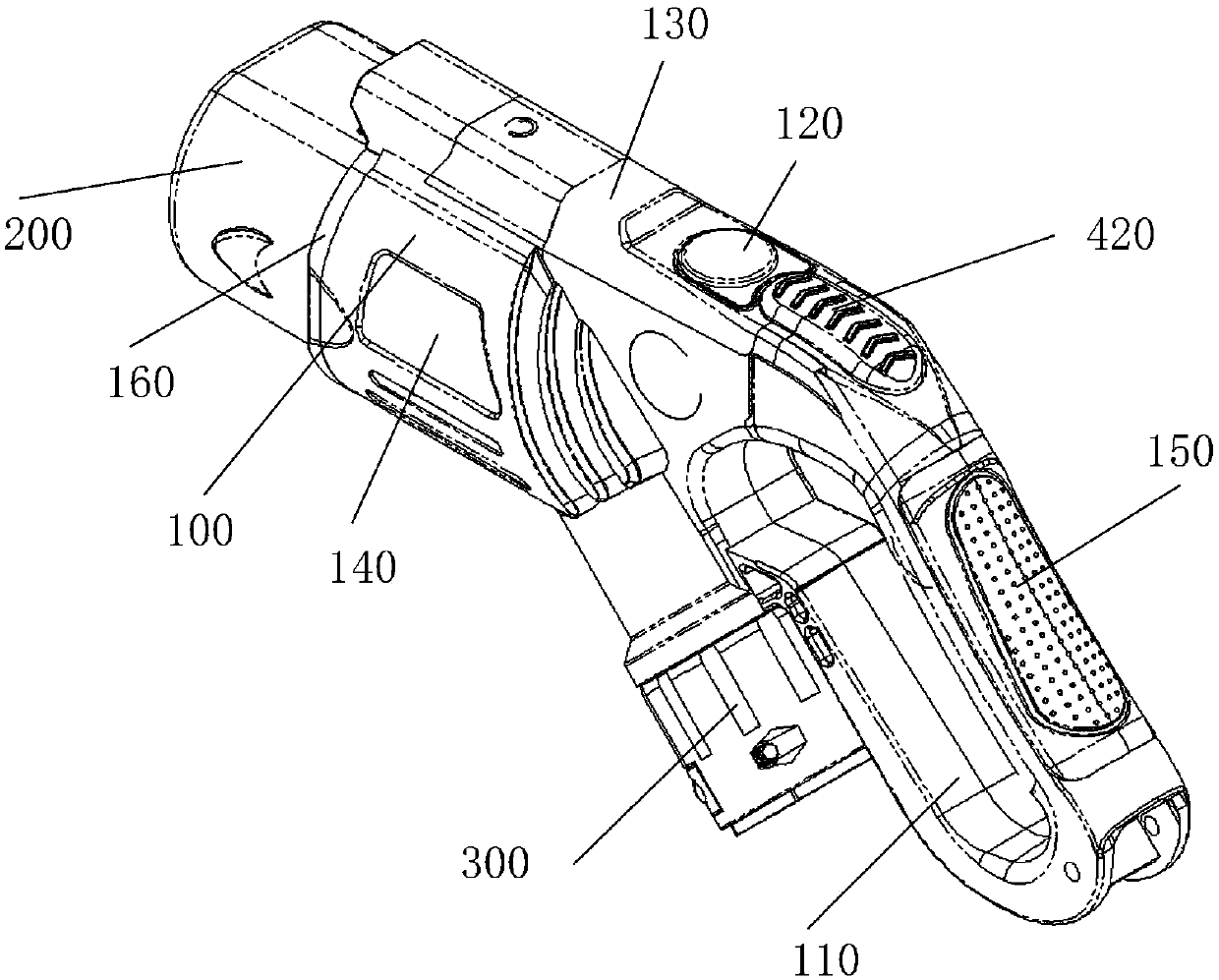
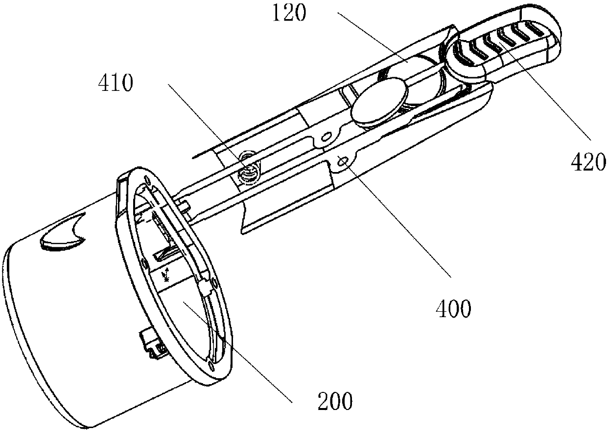
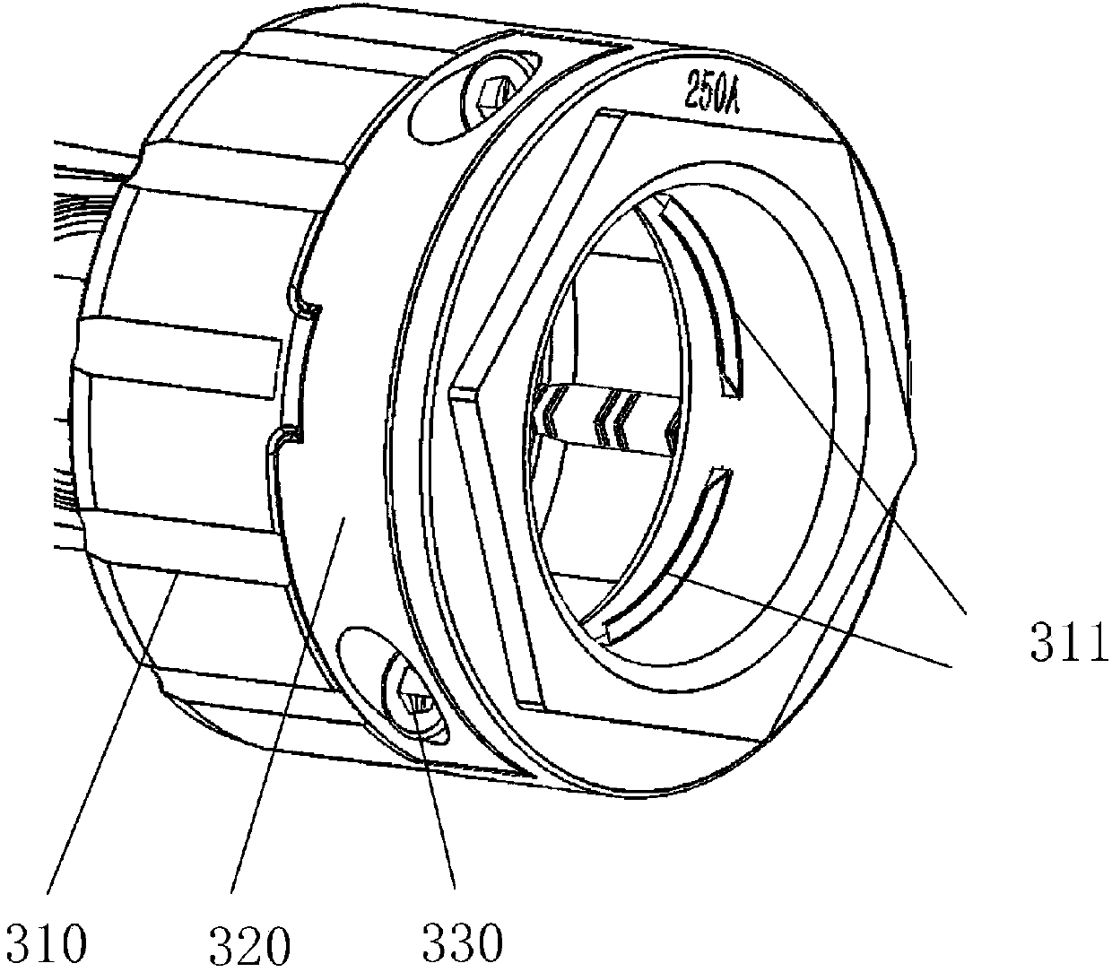
[0027] Such as Figure 1-4 As shown, the present invention is a DC charging gun, which is characterized in that it includes a sheath 100, a handle 110 is provided at the right end of the sheath 100, a plug cover 200 is provided at the left end of the inner cavity of the sheath 100, and the lower left of the inner cavity of the sheath 100 is The end is provided with a cable screw head 300;

[0028] The inner wall of the cavity top of the sheath 100 is movable and f...


PUM


Abstract

The invention discloses a direct-current charging gun. The direct-current charging gun is characterized by comprising a protecting sleeve, wherein a handle is arranged at the right end of the protecting sleeve; a bayonet cap is arranged at the left end of an inner cavity of the protecting sleeve; and a cable screw head is arranged at the lower left end of the inner cavity of the protecting sleeve.In the implementation process of the direct-current charging gun disclosed by the invention, the protecting sleeve is manufactured by adopting a plastic injection integrated forming manner, so that the protecting sleeve is high in sealing performance; the bayonet cap is fixed to the end part of the protecting sleeve, and a waterproof ring is arranged between the protecting sleeve and the bayonetcap, so that when the direct-current charging gun is not used, the sealing performance is improved; according to the direct-current charging gun, a rubber sleeve is pressed, and a pressing rod moves upwards through overcoming the elastic force of a pressure spring, and is no longer in snap-fit with the bayonet cap, so that the bayonet cap is convenient to fix and disassemble; the edge of the rubber sleeve is in sealing connection with an upper cap at the upper part of the protecting sleeve, so that the rubber sleeve is convenient to press, and the sealing performance is good; the cable screw head and the protecting sleeve are separated in the integral structure, and are fixedly sealed with each other; a sliding block is connected to the cable screw head in an inserting manner; and a secondpropping bulge at the inserting connection end of the sliding block and a first propping bulge fixed to the lower part inner wall of the inner cavity of a threaded ring are propped against a sealed fixed cable under the pressing of the torque of bolts.

Description

technical field [0001] The invention relates to the field of EV DC charging systems for new energy electric vehicles, in particular to a DC charging gun. Background technique [0002] Since the release of the 2015 edition of the national standard for the conductive charging system of electric vehicles, the current charging connection device of the old national standard has gradually completely withdrawn from the market, and the new national standard has become the leading technology for the charging connection device of the conductive charging system of electric vehicles. However, due to the differences in the understanding of the technical connotation of the new national standard by the development engineers of different manufacturers and their respective technical levels, the developed charging connection device has the advantages of product appearance, structural concept, functional characteristics, production process, safety and reliability, and product quality. There ar...

Claims


Application Information

Patent Timeline
Patent Type & Authority Applications(China)
IPC IPC(8): B60L11/18
CPCB60L53/16Y02T10/70Y02T10/7072Y02T90/14
Inventor 叶勇刘福良
Owner 浙江汇云光电科技有限公司
Learn More