Shunting pressure relief device

A technology of a pressure relief device and a shunt surface, applied in the field of switch cabinets, can solve the problems of poor blocking effect of hot particles, affecting the overall size of the cabinet, insufficient ventilation rate of the pressure relief device, etc., to achieve the effect of increasing safety.

Pending Publication Date: 2018-04-13
WECOME GRP
View PDF0 Cites 6 Cited by
  • Summary
  • Abstract
  • Description
  • Claims
  • Application Information

AI Technical Summary

Problems solved by technology

However, the cost of the external pressure relief channel is high and will greatly affect the overall size of the cabinet...

Method used


Image

  • Shunting pressure relief device
  • Shunting pressure relief device
  • Shunting pressure relief device

Examples


Embodiment 1

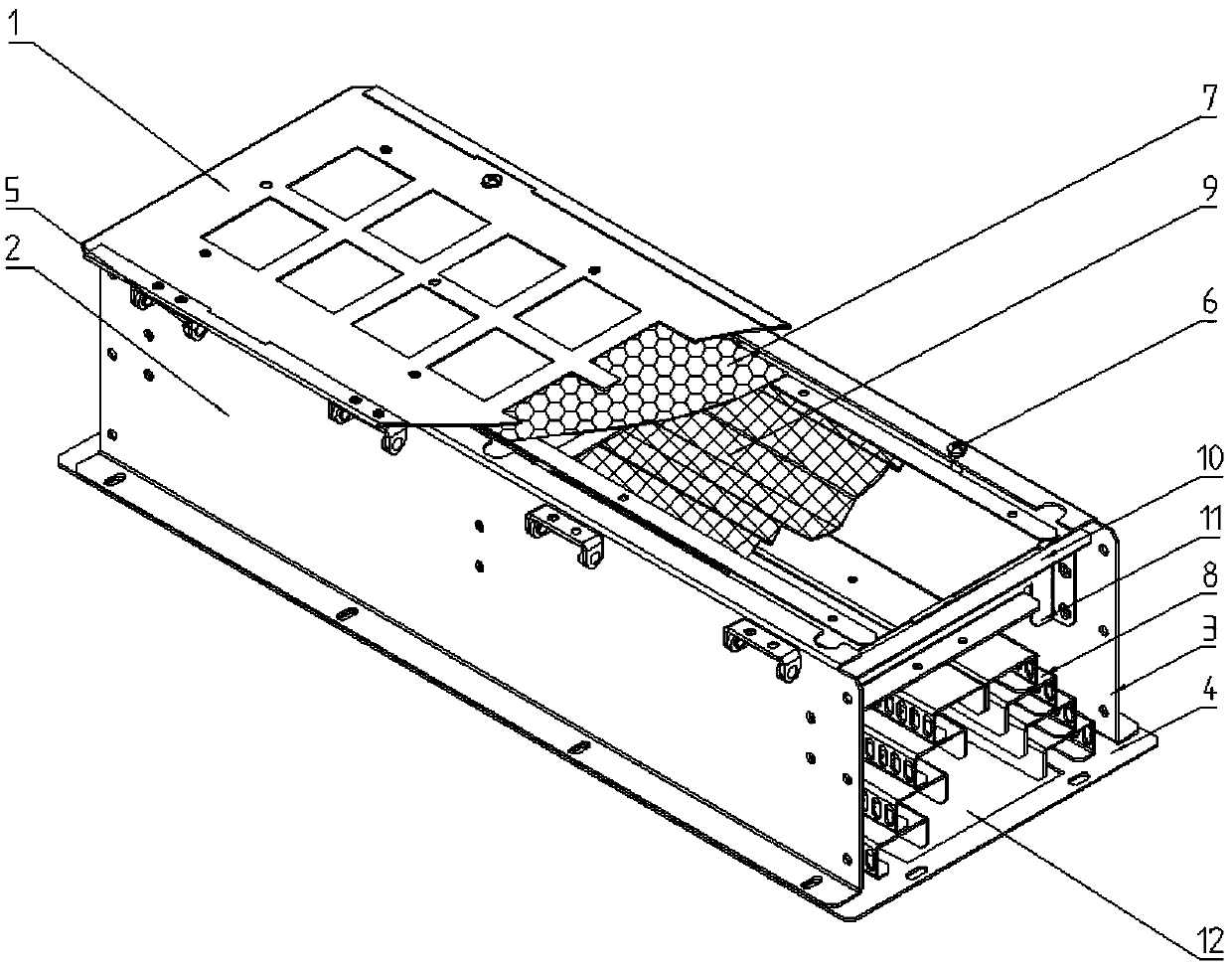
[0023] Embodiment 1, with reference to attached Figure 1-4 .

[0024] In this embodiment, the pressure-dividing device includes a housing, the housing includes a bottom plate 4, a first side plate 2, a second side plate 3 and a top plate 1, the bottom plate 4 is installed on the top of the switch cabinet, and the bottom plate 4 is provided with an inlet The air hole 12 , the top plate 1 and the first side plate 2 are rotatably connected through a hinge 5 .

[0025] The top of the first side plate 2 and the second side plate 3 is provided with inward flanging, and the bottom of the first side plate 2 and the second side plate 3 is provided with outward flanging, so that the first side plate 2 and the second The two side plates 3 form a relative Z shape, and the first side plate 2 and the second side plate 3 are fixedly installed on both sides of the bottom plate 4 by the outward flanging of the bottom respectively, and the flanging on the second side plate 3 tops is provided ...

Embodiment 2

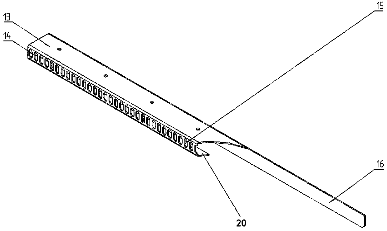
[0034] Embodiment 2, with reference to attached Figure 3-6 .

[0035] In this embodiment, the first side plate 2 and the second side plate 3 are provided with a ventilation grid 23, and the outer side of the ventilation grid 23 is arranged with a protective plate 22, and the protective plate 22 protrudes outwards. The blocking plate 21, the structure of the blocking plate 21 is consistent with the first side plate 2 and the second side plate 3, and the upper part has an inward folded edge, and the lower part has an outward folded edge, and is fixedly connected by the outward folded edge on base plate 4.

[0036] Other implementation modes of this embodiment are the same as Embodiment 1.

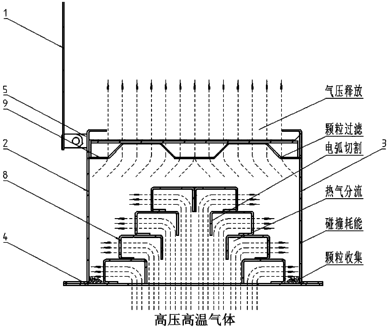
[0037] The working principle of the structure of this embodiment is as Image 6 As shown, when a large amount of high-temperature and high-pressure gas is generated at the bottom of the pressure relief device due to the arcing explosion of the switchgear, the hot gas first enters the pres...


PUM


Abstract

The invention provides a flow diversion and pressure relief device, which includes a housing, and a tower-shaped pressure relief structure is arranged inside the casing. The tower-type pressure relief structure includes flow diversion guide plates stacked in a tower shape. There are ventilation holes on the surface. The beneficial effects of the invention are: the energy of the hot gas is consumed after the device is used, and the scorching particles are filtered, which greatly increases the safety of the switchgear and does not affect the external dimensions of the switchgear.

Description

technical field [0001] The invention relates to a switchgear, in particular to a pressure relief device for a switchgear meeting the requirements of arcing and temperature rise. Background technique [0002] For switchgears currently on the market, external pressure relief channels or similar corrugated pressure relief devices are generally used for high-current short-circuit arcing tests to prevent hot gas and hot particles from damaging the level indicator. However, the cost of the external pressure relief channel is high and will greatly affect the overall size of the cabinet. The ventilation rate of the corrugated pressure relief device is insufficient and the blocking effect on hot particles is poor. Contents of the invention [0003] The technical problem to be solved by the present invention is to provide a pressure relief device for switchgear with low cost, which can effectively block hot particles and meet the requirements of arcing and temperature rise. [0004...

Claims


Application Information

Patent Timeline
IPC IPC(8): H02B1/56H02B1/28H02B13/025H02B1/30
CPCH02B1/28H02B1/306H02B1/565H02B13/025
Inventor 詹华栋金贺啸夏从安向成维
Owner WECOME GRP
Why Eureka
Try Eureka