Turning and spontaneous heating kettle

A hot water bottle, a self-initiated technology, applied to drinking water containers, travel or camping equipment, home appliances, etc., to achieve the effect of simple process, low manufacturing cost, and good development space

Pending Publication Date: 2018-04-20
NORTH CHINA UNIV OF WATER RESOURCES & ELECTRIC POWER
View PDF9 Cites 2 Cited by
  • Summary
  • Abstract
  • Description
  • Claims
  • Application Information

AI Technical Summary

Problems solved by technology

[0003] In view of the current situation that most of the existing water cups must be energized to generate heat, and the problem that so...

Method used


Image

  • Turning and spontaneous heating kettle
  • Turning and spontaneous heating kettle
  • Turning and spontaneous heating kettle

Examples


Embodiment 1

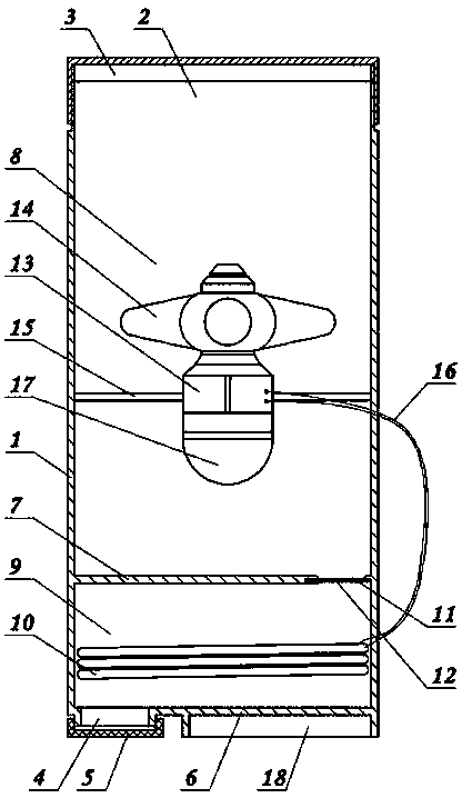
[0019] Embodiment 1: as figure 1 In the flipped self-generating kettle shown, an intermediate layer 7 is provided at the lower part of the cup body 1 , and the cup body 1 is divided into an upper working chamber 8 and a lower heating chamber 9 by the intermediate layer 7 . It can be seen from the figure that the volume of the heating chamber 9 is smaller than that of the working chamber 8 . Therefore, the working chamber 8 can not only store water, but also can do more work for converting electric energy.

[0020] A reversible hydroelectric generator 13 is fixed on the inner wall of the working chamber 8 through a connecting rod, and a resistance wire 10 is installed in the heating chamber 9 . The output power line 16 of the reversible hydroelectric generator 13 is hidden inside the cup body 1 , and the power line 16 is connected to the resistance wire 10 .

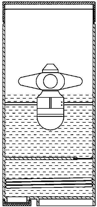
[0021] see figure 2 and Figure 4 As shown, the upper side of the working chamber 8 is provided with a forward cup...

Embodiment 2

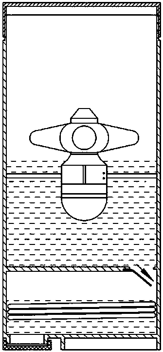
[0025] Embodiment 2: On the basis of Embodiment 1, the reverse cup mouth 4 and the lower cover 5 are arranged on the left side of the cup body 1 , and the drain port 11 and the spring piece 12 are positioned on the right side of the cup body 1 . The two positions are opposite. The purpose of this design is that when pouring hot water outwards, see Figure 5 , at this time, the drain outlet 11 is positioned at the upper side, so the cold water in the working chamber 8 will not directly enter the heating chamber 9, so as to keep pouring out hot water all the time. In an upright position after pouring out hot water see image 3 , the cold water in the working chamber 8 can still enter the heating chamber 9 through the drain port 11 and the shrapnel 12, without affecting the normal drainage function.

Embodiment 3

[0026] Embodiment 3: On the basis of Embodiment 1 or 2, the cup body 1 is a thermos cup with an inner tank, and the bracket for fixing the reversible hydroelectric generator 13 is sleeved on the side wall of the inner tank.

[0027] In order to achieve a better use effect, on the basis of Embodiment 1 or Embodiment 2 or Embodiment 3, a bottom bracket can be arranged below the cup bottom wall 6 of the cup body 1, and the height of the bottom bracket is the same as that of the reverse cup. The mouth 4 and the lower cover 5 have the same height, and the bottom bracket and the reverse cup mouth 4 and the lower cover 5 keep the cup body 1 seated stably.


PUM


Abstract

The invention discloses a turning and spontaneous heating kettle. The kettle comprises a cup body, a generator and an electric resistance wire. A middle partitioning layer inside the cup body dividesthe cup body into an acting cavity in the upper portion and a heating cavity in the lower portion; the hydro-generator is fixed inside the acting cavity, the electric resistance wire is installed inside the heating cavity, and an output power wire of the hydro-generator is connected with the electric resistance wire; a water outlet is formed in the middle partitioning layer, and an elastic piece is installed at the water outlet. Kinetic energy generated during flowing of water inside the kettle can be converted into electric energy through the hydro-generator, then the electric energy is transferred to the electric resistance wire of a heater through the power wire and converted into heat energy through the electric resistance wire, and therefore the purpose that the temperature of the water inside the heating cavity is increased is achieved. The water temperature of the heater can be increased, and the hot water passing through the heater can satisfy the amount of water drunk by people.

Description

technical field [0001] The invention relates to the improvement technology of drinking cups in the field of daily necessities, in particular to a water cup which utilizes hydroelectric power generation and can be used for outdoor survival, cold water heating and hot water heat preservation in daily life. Background technique [0002] As the weather gets colder, ordinary water cups can't keep hot water warm, and ordinary thermos cups can't keep hot water warm for a long time. This bothers many people who want to drink warm water at any time in cold weather. Nowadays, there are external power supply heating thermos cups on the market, that is, directly connecting the power supply to heat the cup body so as to achieve the purpose of heating the water body. When people were in the outdoors, the external power supply type water cup had certain restrictions and limitations in use. Contents of the invention [0003] In view of the current situation that most of the existing wate...

Claims


Application Information

Patent Timeline
IPC IPC(8): A45F3/16A47G19/22
CPCA45F3/16A47G19/2288
Inventor 丁泽霖柴启辉姜珊程哲兰马寿勋何思平李光亚
Owner NORTH CHINA UNIV OF WATER RESOURCES & ELECTRIC POWER
Why Eureka
Try Eureka