Adjusting control mechanism for seat tray
A technology for adjusting control and pallets, which can be applied to chairs, applications, household appliances, etc. It can solve the problems of insufficient support, large backrest support, and small backrest support, etc., to achieve the effect of convenient operation and improved use comfort
- Summary
- Abstract
- Description
- Claims
- Application Information
AI Technical Summary
Problems solved by technology
Method used
Image
Examples
Embodiment 1
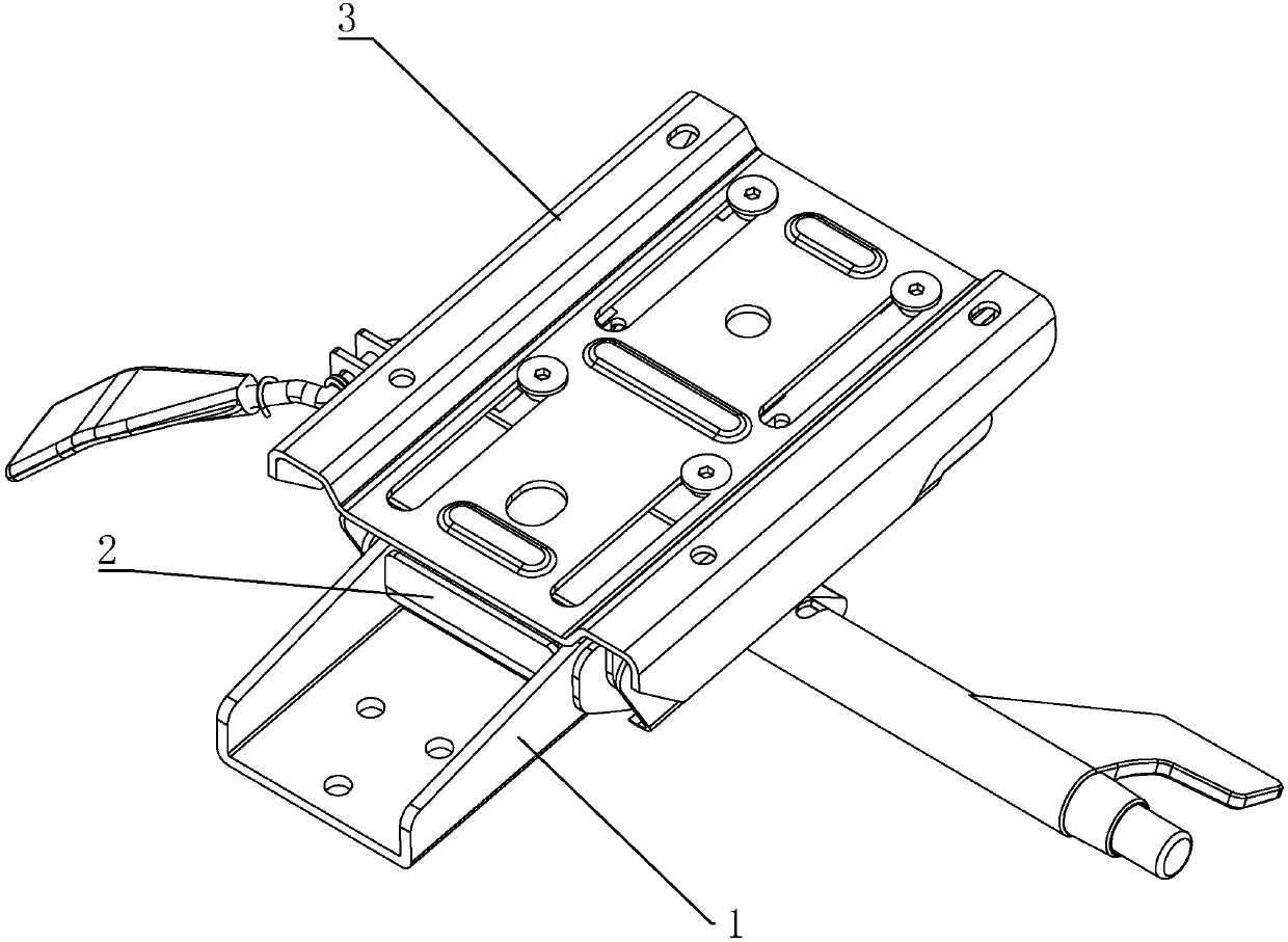
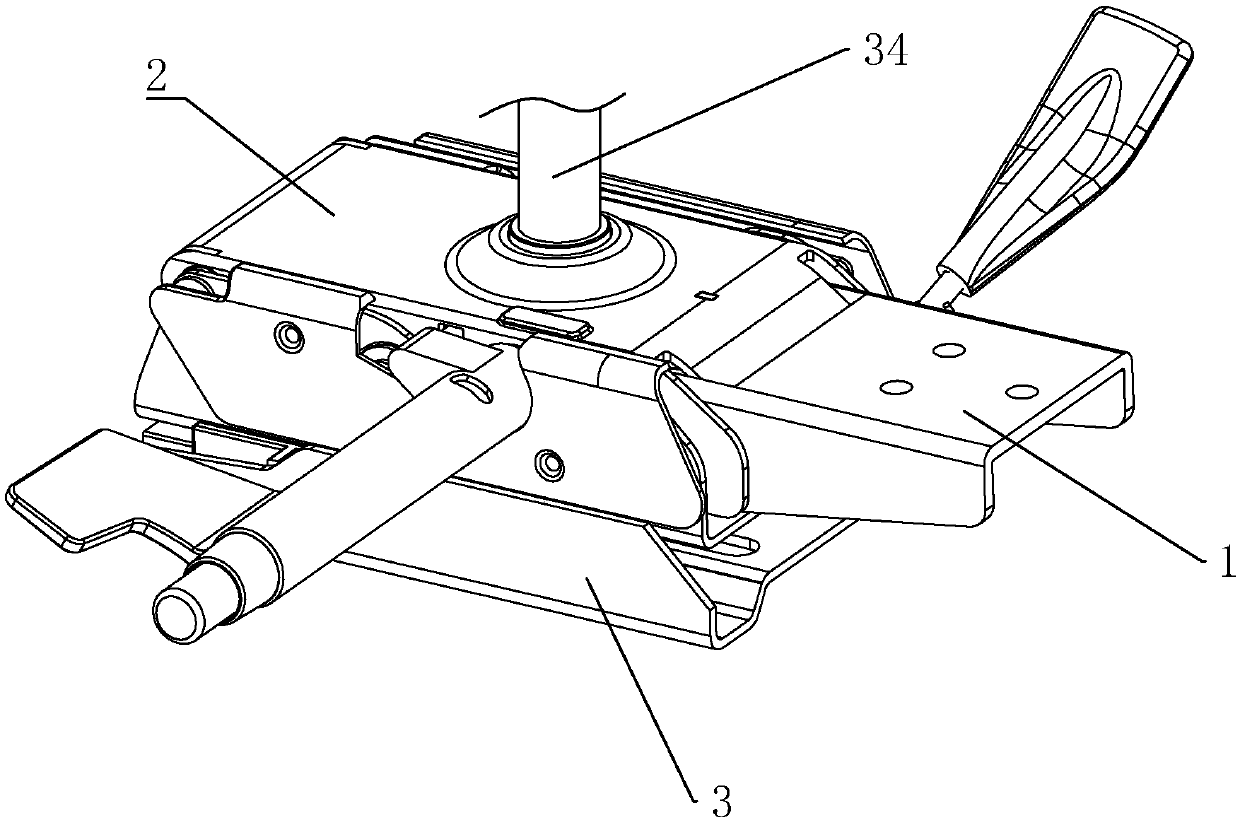
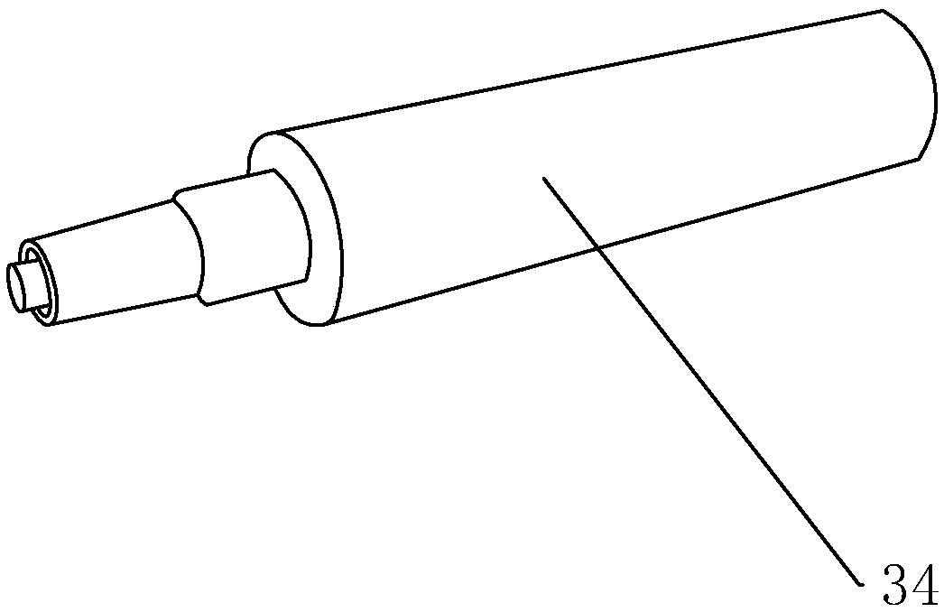
[0045] Such as figure 1 and figure 2 As shown, an adjustment control mechanism for a seat tray includes a moving plate 1, a fixed plate 2 and a base 3, the moving plate 1 is connected to the backrest of the office chair, and the fixed plate 2 is connected to the telescopic member 34 on the office chair . Telescopic part 34 can be air pressure bar (telescopic part 34 is as image 3 shown). The base 3 is connected with the seat board of the office chair. The moving plate 1 is rotatably connected to the fixed plate 2 , and the fixed plate 2 is connected to the base 3 . The inclination angle of the backrest relative to the seat board can be adjusted by turning the rotating disc 1 .
[0046] Such as Figure 4 As shown, a rotating shaft 4 is fixed on the moving disk 1 , and the two ends of the rotating shaft 4 respectively pass through the sidewalls on both sides of the fixed disk 2 and are rotatably connected to the fixed disk 2 . The rotating shaft 4 is fixedly connected t...
Embodiment 2
[0062] The difference between the second embodiment and the first embodiment is that the actuator 15 and the force application member 16 are different. Such as Figure 10 and Figure 11 As shown, the actuator 15 includes an abutment 20 and a first guide 21 , and the force application member 16 includes a second guide 25 and a force application 16 .
[0063] Such as Figure 11 As shown, the actuator 15 includes an abutment 20 and a first guide 21 . Such as Figure 10 As shown, the abutting member 20 abuts against the end of the second segment 19 facing away from the fixed plate 2 , and the abutting member 20 is slidably connected to the guide rail 11 . The abutting member 20 is circumferentially fixed relative to the guide rail 11 . Such as Figure 11 As shown, the first guide member 21 is arranged axially along the guide rail 11 and is fixedly connected to the outer wall of the abutment member 20 . Several first guide members 21 are provided around the abutment member 2...
PUM
 Abstract
Description
Claims
Application Information
 - R&D
- Intellectual Property
- Life Sciences
- Materials
- Tech Scout
- Unparalleled Data Quality
- Higher Quality Content
- 60% Fewer Hallucinations
Browse by: Latest US Patents, China's latest patents, Technical Efficacy Thesaurus, Application Domain, Technology Topic, Popular Technical Reports.
© 2025 PatSnap. All rights reserved.Legal|Privacy policy|Modern Slavery Act Transparency Statement|Sitemap|About US| Contact US: help@patsnap.com


