Painting device for axle tubes

A painting device and shaft tube technology, which is applied in the field of parts painting, can solve the problems of affecting the operation of the staff, the spray paint is contaminated on the hands, and the processing efficiency is low, so as to achieve the effect of ensuring uniformity, easy operation, and improving processing efficiency

Active Publication Date: 2019-06-04
重庆市合川区云天机械制造有限公司
View PDF6 Cites 0 Cited by
  • Summary
  • Abstract
  • Description
  • Claims
  • Application Information

AI Technical Summary

Problems solved by technology

In the existing processing process, when painting the shaft tube, it is necessary to hold the shaft tube and use a spray gun to spray the surface of the shaft tube. After the tool clamps and fixes the shaft tube, the shaft tube is sprayed and processed, but repeated operations of the clamping tool also cause waste of time and low processing efficiency

Method used


Image

  • Painting device for axle tubes
  • Painting device for axle tubes
  • Painting device for axle tubes

Examples


Embodiment Construction

[0020] The present invention will be described in further detail below by means of specific embodiments:

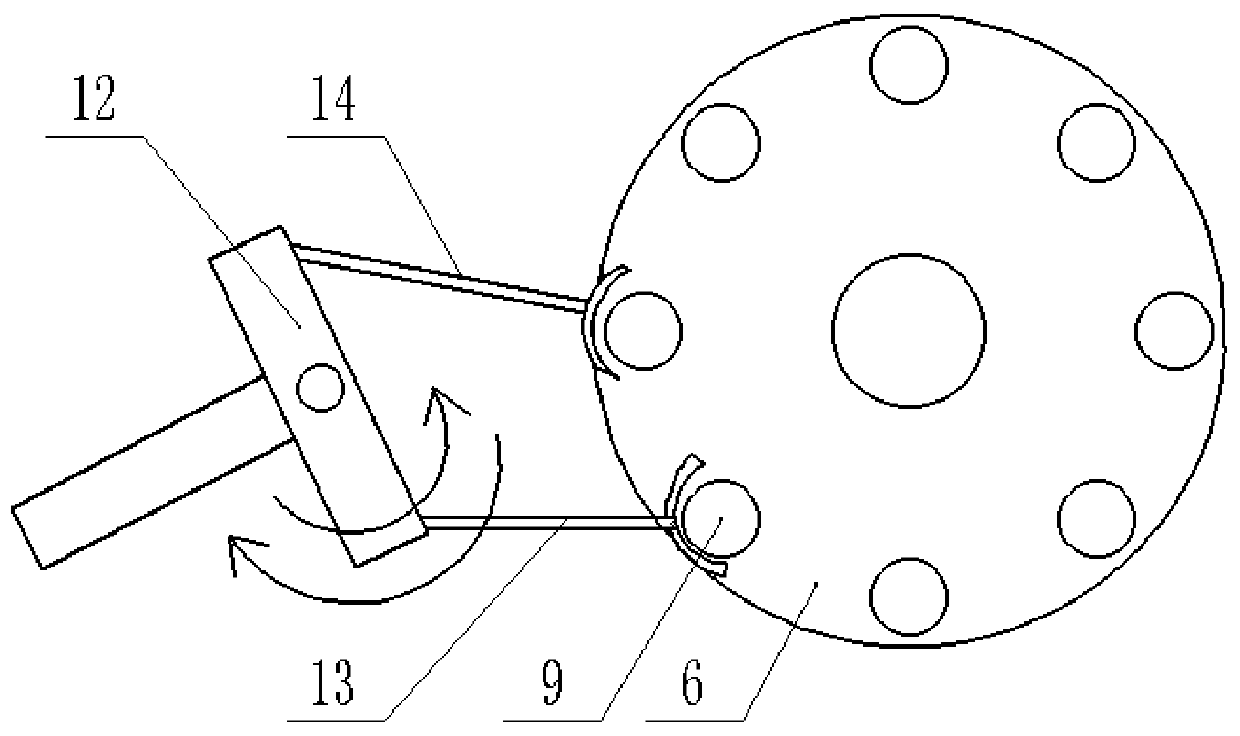
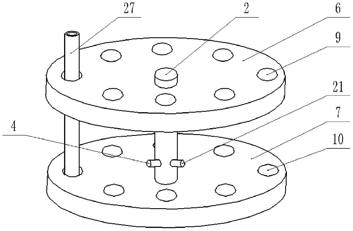
[0021] The reference signs in the accompanying drawings of the description include: processing table 1, axis column 2, paint box 3, paint spray pipe 4, valve 5, first panel 6, second panel 7, support column 8, perforation 9, positioning groove 10 , vertical rod 11, pendulum rod 12, first push arm 13, second push arm 14, arc panel 15, strip hole 16, main gear 17, dial block 18, stirring shaft 19, fan 20, blowing pipe 21, bellows 22, material rack 23, feed gear 24, rack 25, slave gear 26, axle tube 27.

[0022] The embodiment is basically as figure 1 Shown: the painting device for the shaft tube, including the processing table 1, the shaft column 2 is welded on the processing table 1, and the I-shaped turntable is connected to the shaft column 2 through the bearing rotation, such as image 3 As shown, the turntable includes a first panel 6 and a second panel 7 arranged in...


PUM


Abstract

The invention relates to the technical field of part painting and discloses a painting device for a shaft tube. The painting device comprising a machining table and a paint box, an axis column is arranged on the machining table, and an I-shaped rotary disc is rotatably connected to the axis column and comprises a first panel and a second panel. A supporting column is connected between the first panel and the second panel, a plurality of penetrating holes evenly distributed around an axis rod are formed in the first panel, and a plurality of positioning holes rightly facing the penetrating holes in one-to-one mode are formed in the second panel. A vertical rod is arranged on the outer side of the rotary disc, the two ends of the vertical rod are fixedly connected with a swing rod and a cambered plate correspondingly, and a first push arm and a second push arm are hinged to the swing rod. A strip-shaped hole is formed in the cambered plate, the paint box comprises a paint spraying tube,the paint spraying tube extends between the first panel and the second panel, and a main gear is rotatably connected to the paint box. A shifting block is connected to the main gear and slidably connected into the strip-shaped hole, and the paint box is internally provided with a stirring shaft fixedly connected with the main gear. Through the painting device, shaft tube batch fixing and paintingmachining can be achieved, and the machining efficiency is improved.

Description

technical field [0001] The invention relates to the technical field of part painting, in particular to a painting device for a shaft tube. Background technique [0002] During the production and processing of shaft tube parts, in order to ensure the processing quality of the parts, it is often necessary to smear the outside of the parts with paint to prevent the shaft parts from being oxidized and rusted and destroying the practical effect of the parts. In the existing processing process, when painting the shaft tube, it is necessary to hold the shaft tube and use a spray gun to spray the surface of the shaft tube. After the tool clamps and fixes the shaft tube, the shaft tube is sprayed and processed, but repeated operations of the clamping tool also cause waste of time and low processing efficiency. Contents of the invention [0003] The invention intends to provide a painting device for shaft tubes, so as to realize batch fixing and painting processing of shaft tubes a...

Claims


Application Information

Patent Timeline
Patent Type & Authority Patents(China)
IPC IPC(8): B05B13/02B05B15/25B05B16/20
CPCB05B13/025
Inventor 张科
Owner 重庆市合川区云天机械制造有限公司
Why Eureka
Try Eureka