Metal material cutting equipment for hardware tool production

A technology for metal materials and cutting equipment, applied in metal processing equipment, shearing equipment, manufacturing tools, etc., can solve the problems of low cutting efficiency and complicated operation, and achieve the effect of fast cutting

Inactive Publication Date: 2018-04-20
王森杰
View PDF7 Cites 4 Cited by
  • Summary
  • Abstract
  • Description
  • Claims
  • Application Information

AI Technical Summary

Problems solved by technology

[0005] In order to overcome the shortcomings of complex operation and low cutting efficiency in the current metal material cutting device for hardware tool production, the technical problem to be solved by the present invention is to provide a metal material cutting equipment for hardware tool production with simple operation and high cutting efficiency

Method used


Image

  • Metal material cutting equipment for hardware tool production
  • Metal material cutting equipment for hardware tool production
  • Metal material cutting equipment for hardware tool production

Examples


Embodiment 1

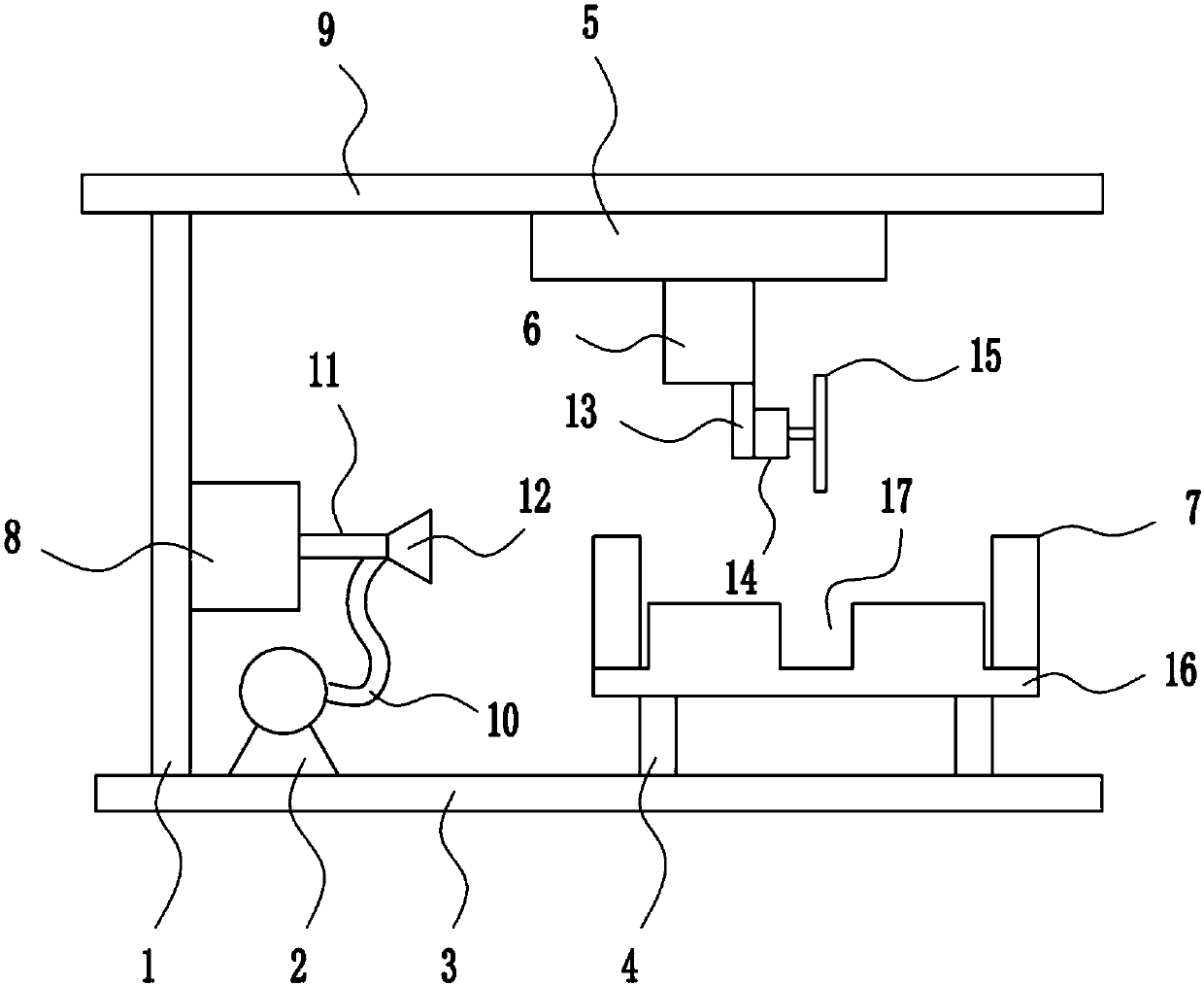
[0037] A metal material cutting equipment for the production of hardware tools, such as Figure 1-6 As shown, it includes a left frame 1, an air pump 2, a bottom plate 3, a strut 4, a moving device 5, a lifting device 6, a clamping device 7, a swing device 8, a top plate 9, an air pipe 10, a fixed sleeve 11, a nozzle 12, a fixed The plate 13, the rotating motor 14, the blade 15 and the operating table 16, a left frame 1 is welded on the left side of the top of the bottom plate 3, a swing device 8 is arranged in the middle of the right side of the left frame 1, and a fixed sleeve 11 is welded on the right side of the swing device 8. The fixed sleeve 11 A spray head 12 is fixed on the right side, an air pump 2 is connected to the left side of the top of the bottom plate 3 by means of bolt connection, the air pump 2 is located on the right side of the left frame 1, and an air pipe 10 is connected between the air pump 2 and the spray head 12 by means of flange connection, A suppor...

Embodiment 2

[0039] A metal material cutting equipment for the production of hardware tools, such as Figure 1-6 As shown, it includes a left frame 1, an air pump 2, a bottom plate 3, a strut 4, a moving device 5, a lifting device 6, a clamping device 7, a swing device 8, a top plate 9, an air pipe 10, a fixed sleeve 11, a nozzle 12, a fixed The plate 13, the rotating motor 14, the blade 15 and the operating table 16, a left frame 1 is welded on the left side of the top of the bottom plate 3, a swing device 8 is arranged in the middle of the right side of the left frame 1, and a fixed sleeve 11 is welded on the right side of the swing device 8. The fixed sleeve 11 A spray head 12 is fixed on the right side, an air pump 2 is connected to the left side of the top of the bottom plate 3 by means of bolt connection, the air pump 2 is located on the right side of the left frame 1, and an air pipe 10 is connected between the air pump 2 and the spray head 12 by means of flange connection, A suppor...

Embodiment 3

[0042] A metal material cutting equipment for the production of hardware tools, such as Figure 1-6 As shown, it includes a left frame 1, an air pump 2, a bottom plate 3, a strut 4, a moving device 5, a lifting device 6, a clamping device 7, a swing device 8, a top plate 9, an air pipe 10, a fixed sleeve 11, a nozzle 12, a fixed The plate 13, the rotating motor 14, the blade 15 and the operating table 16, a left frame 1 is welded on the left side of the top of the bottom plate 3, a swing device 8 is arranged in the middle of the right side of the left frame 1, and a fixed sleeve 11 is welded on the right side of the swing device 8. The fixed sleeve 11 A spray head 12 is fixed on the right side, an air pump 2 is connected to the left side of the top of the bottom plate 3 by means of bolt connection, the air pump 2 is located on the right side of the left frame 1, and an air pipe 10 is connected between the air pump 2 and the spray head 12 by means of flange connection, A suppor...


PUM


Abstract

The invention relates to cutting equipment, in particular to metal material cutting equipment for hardware tool production, aims to provide the metal material cutting equipment for hardware tool production, and the metal material cutting equipment is simple to operate and high in cutting efficiency. The metal material cutting equipment comprises a left frame, an air pump, a bottom plate, supporting rods, a moving device, a lifting device, a clamping device, a swinging device, a top plate and the like, wherein the left frame is welded to the left side of the top of the bottom plate, the swinging device is arranged in the middle of the right side of the left frame, a fixed sleeve is welded to the right side of the swinging device, and a spray head is fixed on the right side of the fixed sleeve. According to the metal material cutting equipment, the rotating direction of a first electric wire winding wheel is controlled, the first electric wire winding wheel and a first spring are matchedwith each other, and therefore a blade can move back and forth, and the effect of fast cutting is achieved; and the extension and the shortening of a first electric push rod are controlled, a special-shaped gear is matched with a first rack, and therefore the height of the blade can be adjusted.

Description

technical field [0001] The invention relates to a cutting device, in particular to a metal material cutting device for the production of hardware tools. Background technique [0002] Hardware: Traditional hardware products, also known as "small hardware". Refers to the five metals of gold, silver, copper, iron and tin. After manual processing, it can be made into art or metal devices such as knives and swords. Hardware in modern society is more extensive, such as hardware tools, hardware parts, daily hardware, construction hardware and security supplies. Most hardware products are not final consumer goods. Today's hardware is often referred to as a general term for products such as metal or copper and iron. The further application of metals has played an important role in the development of the history of human civilization and society. Metal products appear in every corner of economic life, political life and military activities. History has entered the modern industr...

Claims


Application Information

Patent Timeline
Patent Type & Authority Applications(China)
IPC IPC(8): B23D19/00B23D33/00B23Q5/28B23Q11/00
CPCB23D19/00B23D33/00B23Q5/28B23Q11/005
Inventor 王森杰林正深周鹏
Owner 王森杰
Why Eureka
Try Eureka