
Rectification assembly suitable for multi-load missile and missile

A multi-load and payload technology, applied in self-propelled projectiles, projectiles, offensive equipment, etc., can solve the problems of inability to meet the flexible configuration of multi-load, limit the lightweight and reliability of missiles, and the physical constraints of the load shape envelope. Achieve the effect of avoiding additional mass, meeting lightweight requirements, and eliminating physical constraints

Active Publication Date: 2018-04-20
CHINA ACAD OF LAUNCH VEHICLE TECH
View PDF4 Cites 0 Cited by
  • Summary
  • Abstract
  • Description
  • Claims
  • Application Information

AI Technical Summary

Problems solved by technology

[0004] With the improvement of missile carrying capacity, multi-load form has become the development trend of missiles. With the emergence of multi-load missiles, the existence of fairings has great physical constraints on the envelope of load shapes, which cannot meet the requirements of flexible configuration of multiple loads. At the same time, due to the existence of the fairing, the lightweight and reliability of the missile are limited.

Method used


Image

  • Rectification assembly suitable for multi-load missile and missile
  • Rectification assembly suitable for multi-load missile and missile
  • Rectification assembly suitable for multi-load missile and missile

Examples


Embodiment 1

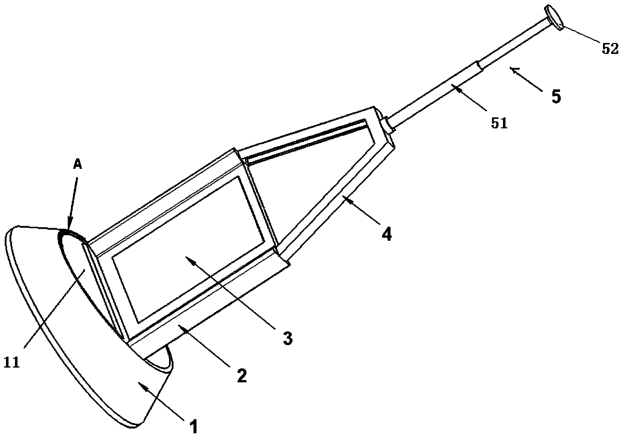
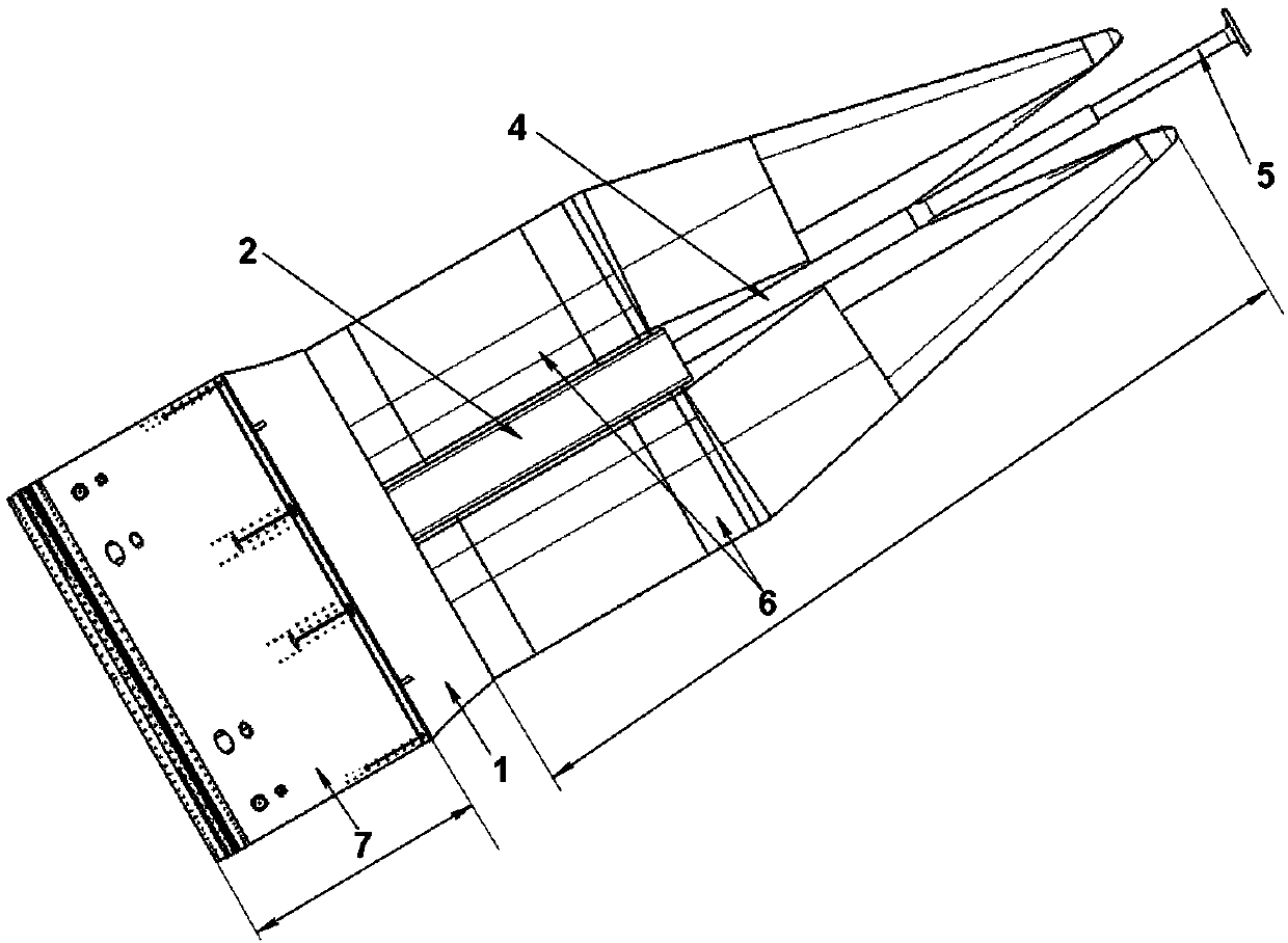
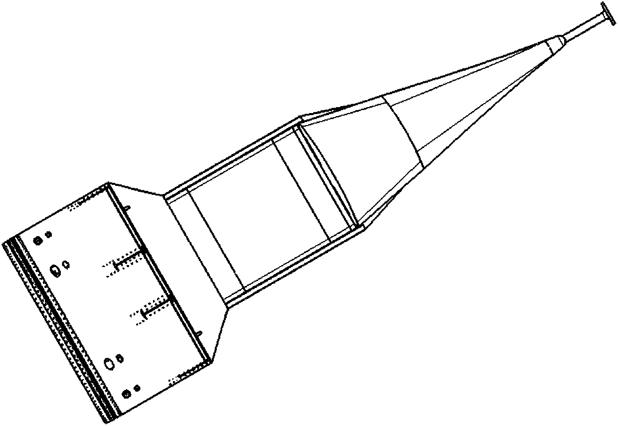
[0047] This embodiment provides a rectifying assembly of a dual-load missile, such as figure 2 As shown, the rectification assembly includes a load bracket 1, a cushion block 3, a support frame 2, a rectification rod bracket 4 and a rectification rod 5; as figure 1 As shown, the load bracket 1 is a hollow structure with a variable cross-section, the first end of the load bracket 1 is circular, and its outer diameter is consistent with the outer diameter of the missile cabin. The second end of the load bracket 1 is provided with two mounting holes 11, and other The position is closed; the two loads 6 are symmetrically installed on the load bracket 1 through two mounting holes 11 respectively, and the flatness of the mounting surface of the load 6 and the load bracket 1 is 0.1; The middle position of the second end face of the bracket 1 makes the two loads 6 separate on both sides; the rectifying rod bracket 4 is connected with the second end of the load bracket 1 through the s...


PUM


Abstract

The invention provides a rectification assembly suitable for a multi-load missile and the missile and belongs to the field of overall design of missiles. The missile comprises at least two loads. Therectification assembly comprises a load bracket, a rectification rod bracket and a rectification rod. The load bracket is of a variable-section hollow structure, the outer diameter of the first end ofthe load bracket accords with that of a missile bin section, and the second end of the load bracket is a closed end and is provided with mounting holes with the number being matched with that of theloads. The loads are symmetrically mounted on the load bracket through the mounting holes, and the rectification rod bracket is connected with the second end of the load bracket. The rectification rodcomprises a supporting rod and a disc, the disc is connected with the rectification rod bracket through the supporting rod, the rectification rod is located in the symmetrical center of the at leasttwo loads, and the disc is located in front of the loads in the flight state. The purpose of rectification resistance reduction is achieved by directly arranging the rectification rod, the additionalassociated mass brought by using of a fairing is avoided, the lightweight requirement of the missile is met, and the reliability of the multi-load missile is improved.

Description

technical field [0001] The invention relates to the technical field of missile overall design, in particular to a missile rectification device with multi-task load. Background technique [0002] When the missile is in flight, it will encounter high resistance and harsh thermal environment, which will lead to the failure of the missile load. Therefore, it is necessary to install a rectification component on the head of the missile to ensure the normal flight of the missile. [0003] Existing fairing assemblies generally include a fairing and its separation. [0004] With the improvement of missile carrying capacity, multi-load form has become the development trend of missiles. With the emergence of multi-load missiles, the existence of fairings has great physical constraints on the envelope of load shapes, which cannot meet the requirements of flexible configuration of multiple loads. At the same time, due to the existence of the fairing, the lightweight and reliability of t...

Claims


Application Information

Patent Timeline
Patent Type & Authority Applications(China)
IPC IPC(8): F42B15/00F42B10/38
CPCF42B10/38F42B15/00
Inventor 曾亮陈升泽俞启东陈雪冬惠俊鹏郑小鹏裴胤
Owner CHINA ACAD OF LAUNCH VEHICLE TECH
Learn More