Camera installation structure of mobile terminal and mobile terminal

A technology of mobile terminal and installation structure, which is applied in the direction of telephone structure, image communication, color TV parts, etc. It can solve the problem that the camera and the display screen cannot be overlapped, the area where the camera is located cannot provide display, and the imaging quality of the front camera Low-level problems, to achieve the effect of ultra-narrow bezel or even no bezel, improve product performance, and increase screen-to-body ratio

Inactive Publication Date: 2018-04-20
GUANGDONG OPPO MOBILE TELECOMM CORP LTD
View PDF5 Cites 8 Cited by
  • Summary
  • Abstract
  • Description
  • Claims
  • Application Information

AI Technical Summary

Problems solved by technology

Using mobile phones to take selfies has become a routine habit of many mobile phone users. The front camera is widely used in self-phobic scenes. The mobile phone camera must have a light path, so the traditional camera and the display screen cannot Overlapping settings, because the display screen will block light from entering the camera, and the camera has a certain volume. When the camera and the display screen are arranged in a staggered manner, the camera occupies a certain space, so the area where the camera is located cannot provide display. This is also the case on conventional mobile phones. An important reason for the relatively large black border
[0005] At the same time, installing a front camera and a rear camera on a smartphone will inevitably increase the cost of the camera, increase the overall weight and thickness of the phone, and make it difficult to make the phone thinner.
Generally, in order to save the cost of the camera, mobile phone manufacturers usually use low-pixel cameras with low image quality for the front camera, and the poor image quality brings poor experience to customers.

Method used


Image

  • Camera installation structure of mobile terminal and mobile terminal
  • Camera installation structure of mobile terminal and mobile terminal
  • Camera installation structure of mobile terminal and mobile terminal

Examples


Embodiment 1

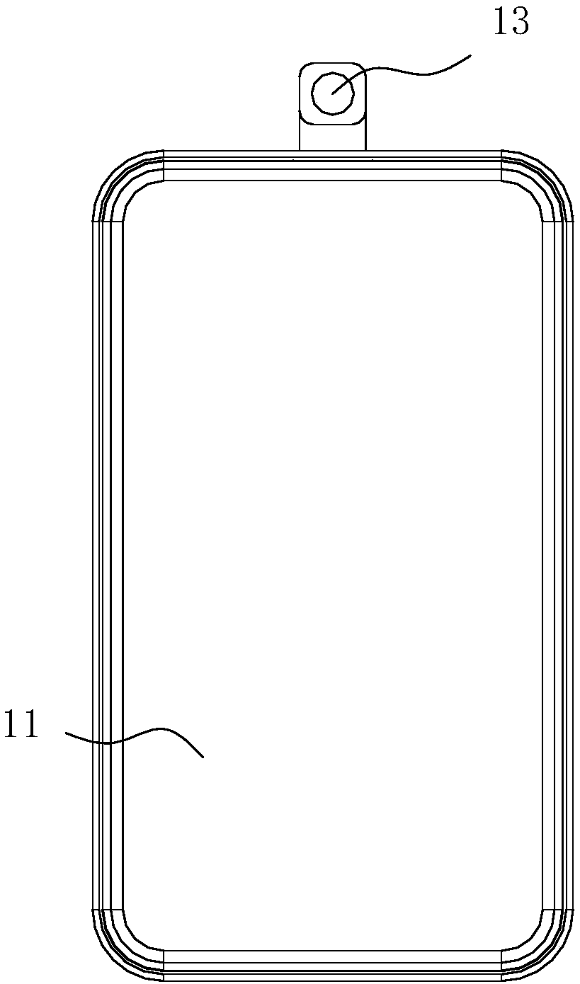
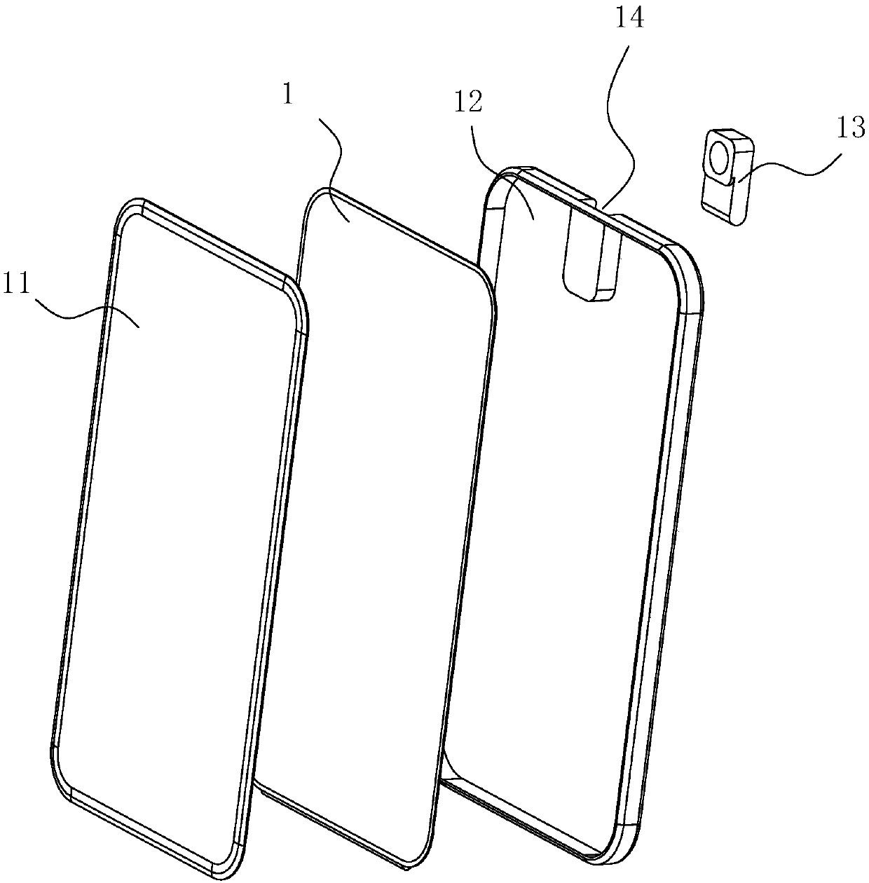
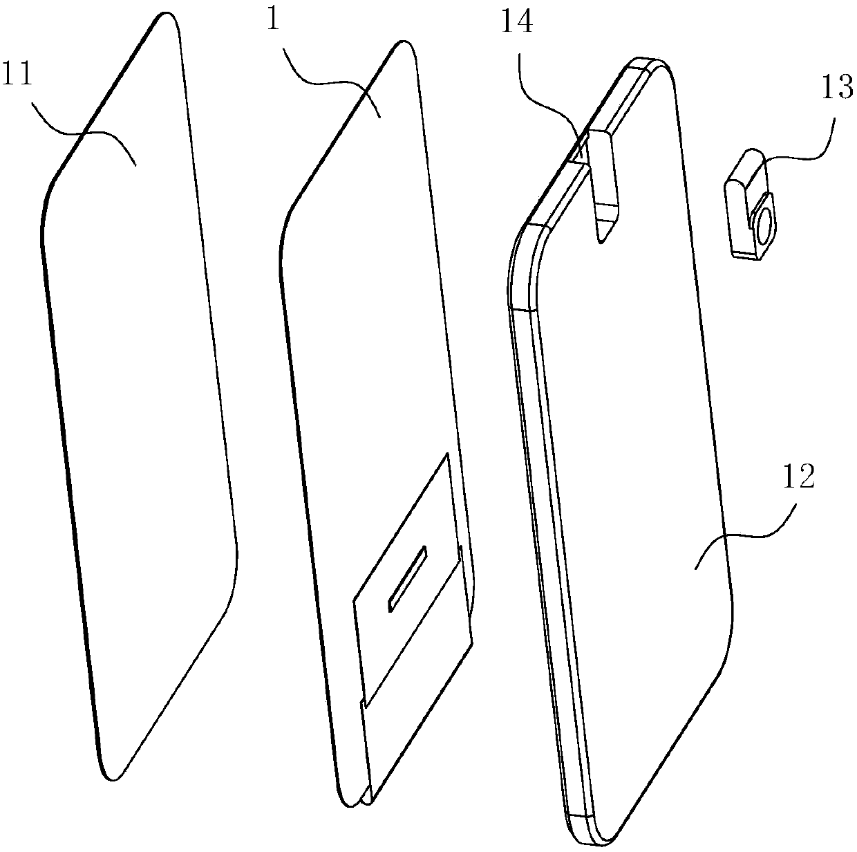
[0035] Such as Figures 1 to 7 As shown, in this embodiment, a camera installation structure of a mobile terminal according to the present invention includes a terminal housing 12 and a display assembly arranged on the surface of the terminal housing 12, and the display assembly includes an integrated A display screen composed of a display area of ​​the structure and a non-display area, the display area is used to display images, the non-display area is used to connect the control circuit, the non-display area is located below the display area, so that the The outline of the display area is used as the display outline of the mobile terminal. The rear camera module 13 is arranged on the back of the terminal housing, and the rear camera module 13 is rotatably arranged relative to the mobile terminal. When shooting, the rear camera module 13 can be turned over to the top of the mobile terminal as a front camera.

[0036] The bottom in this embodiment refers to the side of the di...

Embodiment 2

[0041] Such as Figures 1 to 7 As shown, in this embodiment, a camera installation structure of a mobile terminal according to the present invention includes a terminal housing 12 and a display assembly arranged on the surface of the terminal housing 12, and the display assembly includes an integrated A display screen composed of a display area of ​​the structure and a non-display area, the display area is used to display images, the non-display area is used to connect the control circuit, the non-display area is located below the display area, so that the The outline of the display area is used as the display outline of the mobile terminal. The rear camera module 13 is arranged on the back of the terminal housing, and the rear camera module 13 is rotatably arranged relative to the mobile terminal. When shooting, the rear camera module 13 can be turned over to the top of the mobile terminal as a front camera.

[0042] The bottom in this embodiment refers to the side of the di...

Embodiment 3

[0046] Such as Figures 1 to 7 As shown, in this embodiment, a camera installation structure of a mobile terminal according to the present invention includes a terminal housing 12 and a display assembly arranged on the surface of the terminal housing 12, and the display assembly includes an integrated A display screen composed of a display area of ​​the structure and a non-display area, the display area is used to display images, the non-display area is used to connect the control circuit, the non-display area is located below the display area, so that the The outline of the display area is used as the display outline of the mobile terminal. The rear camera module 13 is arranged on the back of the terminal housing, and the rear camera module 13 is rotatably arranged relative to the mobile terminal. When shooting, the rear camera module 13 can be turned over to the top of the mobile terminal as a front camera.

[0047] The bottom in this embodiment refers to the side of the di...


PUM


Abstract

The invention discloses a camera installation structure of a mobile terminal. The camera installation structure comprises a terminal shell and a display component arranged on the surface of the terminal shell; the display component comprises a display screen composed of a display area with an integrated structure and a non-display area, wherein the display area is used for displaying images; the non-display area is used for connecting a control circuit; the display screen is a flexible OLED (Organic Light-Emitting Diode) screen; the non-display area is arranged below the display area by folding to make the outline of the display area as the display outline of the mobile terminal, thereby realizing the display of the images on the whole surface of the display screen; a rear camera module isarranged at the back of the terminal shell, wherein the rear camera module is rotationally arranged relative to the terminal shell; and during front shooting, the rear camera module can be turned over to the upper part of the mobile terminal to be used as a front camera. A mobile phone can achieve front-side full screen display; the screen-to-body ratio is high, high definition shooting in the front and rear sides can be achieved, and the production cost is low.

Description

[0001] This application is a divisional application of a patent with the application number 201611034340.1, the application date on November 16, 2016, and the invention name "A camera installation structure for a mobile terminal and a mobile terminal". technical field [0002] The invention relates to the technical field of mobile electronic communication equipment, in particular to a camera installation structure of a mobile terminal and a mobile terminal adopting the installation structure. Background technique [0003] Electronic products such as smart phones have occupied the vast majority of the mobile phone market with their powerful functions. Display screens are an indispensable human-computer interaction tool for smart phones. The performance and beauty of the display directly affect the actual experience of users. From the perspective of visual effects, although the current smart phone display screen can realize a larger screen display, due to the limitation of mobi...

Claims


Application Information

Patent Timeline
Patent Type & Authority Applications(China)
IPC IPC(8): H04M1/02H04N5/225
CPCH04M1/0264H04M1/0266H04N23/57
Inventor 成蛟
Owner GUANGDONG OPPO MOBILE TELECOMM CORP LTD
Why Eureka
Try Eureka