
Ranging device and ranging method based on constant threshold value identification method

The technology of a distance measuring device and a distance measuring method, which is applied in the field of laser measurement, can solve the problems of time drift error, different echo intensity, output time time drift error, etc., and achieve the effect of correcting drift error and simple method

Active Publication Date: 2018-04-24
NANJING UNIV OF SCI & TECH
View PDF10 Cites 11 Cited by
  • Summary
  • Abstract
  • Description
  • Claims
  • Application Information

AI Technical Summary

Benefits of technology

This new technology helps improve the performance of an electronic device by accurately measuring its position or motion during operation. It uses measurements taken at different times for comparison instead of just comparing them once every few milliseconds (ms). These techniques help prevent errors caused by factors like changes in reflective properties that may affect signal strengths when transmitted signals are reflected back into their original form after being captured by sensors placed near it's surface.

Problems solved by technology

This patented describes how pulsed Lasers are commonly used to measure distances accurately without requiring complex equipment or multiple measurements. However, these techniques have limitations because they can cause variations in timing caused by factors like temperature fluctuations (temperature) and humidity. These issues affect their accuracy and effectiveness over long periods of use.

Method used


Image

  • Ranging device and ranging method based on constant threshold value identification method
  • Ranging device and ranging method based on constant threshold value identification method
  • Ranging device and ranging method based on constant threshold value identification method

Examples


Embodiment 1

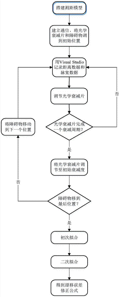
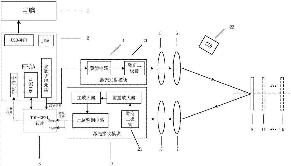
[0050] combine figure 2 , to build the ranging device, the obstacles are located at the actual distance d from the ranging device i = 5 meters, 10 meters, 15 meters... 45 meters, 50 meters, at each actual distance position, the polarizer starts to adjust from 0°, and adjusts 2° each time, until the optical attenuator completes an attenuation cycle and returns to The initial attenuation degree, at each attenuation degree, the distance to the obstacle and the pulse width of the echo are continuously collected 2000 times, and the average value t of the 2000 distance data is obtained ij and the mean value w of the pulse width data ij , each actual distance position collects a set of distance mean data t i and pulse width average data w i , so a total of 10 sets of distance mean data t are collected i and pulse width average data w i .

[0051] 10 sets of distance data t i and pulse width data w i Substitute the following relational model

[0052]

[0053] Fitting is p...


PUM


Abstract

The invention discloses a ranging device and ranging method based on a constant threshold value identification method. In the pulse laser ranging device based on the constant threshold value identification method, an optical attenuator is utilized for adjusting pulse laser emergent intensity and the barrier distance is changed; the measurement distance and pulse width in different distance and indifferent laser intensity are recorded continuously and primary fitting and secondary fitting are performed on distance data and pulse width data, and a ranging formula subjected to finally drift error correction is obtained. Time drift errors caused by single threshold values are compensated and precision influence on pulse laser ranging based on the constant threshold value identification methoddue to echo energy change can be reduced. Besides, circuit complexity is not increased and the method is simple in implementation.

Description


Claims


Application Information

Patent Timeline
Owner NANJING UNIV OF SCI & TECH
Learn More