Distance measuring method and device based on ultrasonic waveform oscillation starting characteristics

A distance measurement method, ultrasonic technology, applied in the direction of measuring device, sound wave reradiation, radio wave measurement system, etc., can solve the problems of extracting waveform points, large errors, and calculating received signals, etc., and achieve the effect of improving accuracy

Pending Publication Date: 2021-12-03
GUOCHUANG INNOVATION CENTER OF MOBILE ENERGY (JIANGSU) CO.,LTD.
View PDF6 Cites 0 Cited by
  • Summary
  • Abstract
  • Description
  • Claims
  • Application Information

AI Technical Summary

Problems solved by technology

[0003] At present, the commonly used threshold method is to mark the point at which the received waveform reaches the threshold as the starting point of the receiving probe, which has a large error, and the amplitude of the ultrasonic received waveform is affected by the distance and angle of the receiving and transmitting probes; Use the envelope peak point of the ultrasonic received signal or use the sine-like characteristics of the ultrasonic signal to generate a zero-crossing signal to calculate the start-up time of the received signal. However, the peak point of the ultrasonic received signal fluctuates, and there will be one or half The deviation of the period, taking the 40KHz ultrasonic wave as an example, a period of 25us, is an error of 8.5mm; in addition, using the zero-crossing detection method, since the amplitude of the ultrasonic signal is affected by the distance and angle of the transmitting and receiving probes, The pulse width of the square wave and the position of the first square wave of the generated zero-crossing detection signal are fluctuating, which is not conducive to using the pulse width of the square wave or the position of the first square wave to extract a fixed waveform point to calculate and receive signal start time

Method used


Image

  • Distance measuring method and device based on ultrasonic waveform oscillation starting characteristics
  • Distance measuring method and device based on ultrasonic waveform oscillation starting characteristics
  • Distance measuring method and device based on ultrasonic waveform oscillation starting characteristics

Examples


Embodiment Construction

[0027] The following will clearly and completely describe the technical solutions in the embodiments of the present invention with reference to the accompanying drawings in the embodiments of the present invention. Obviously, the described embodiments are only some, not all, embodiments of the present invention. Based on the embodiments of the present invention, all other embodiments obtained by persons of ordinary skill in the art without making creative efforts belong to the protection scope of the present invention.

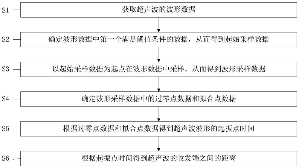
[0028] figure 1 It is a flow chart of the distance measuring method based on the oscillation characteristic of the ultrasonic wave according to the embodiment of the present invention.

[0029] like figure 1 As shown, the ranging method based on the ultrasonic waveform vibration characteristic of the embodiment of the present invention includes the following steps:

[0030] S1. Obtain ultrasonic wave data.

[0031] Specifically, the waveform data of the ult...


PUM


Abstract

The invention provides a distance measuring method and device based on ultrasonic waveform oscillation starting characteristics, and the method comprises the following steps of obtaining the waveform data of ultrasonic waves; determining the first data meeting a threshold condition in the waveform data so as to obtain the initial sampling data; sampling in the waveform data by taking the initial sampling data as a starting point so as to obtain the waveform sampling data; determining the zero crossing point data and the fitting point data in the waveform sampling data; obtaining the oscillation starting point time of the ultrasonic waveform according to the zero crossing point data and the fitting point data; and obtaining the distance between the receiving and transmitting ends of the ultrasonic waves according to the oscillation starting point time. According to the invention, the periodic characteristics of the received waveform are used for calculation, so that the influence of the distance between the ultrasonic receiving and transmitting ends and a correlation angle on the distance measurement precision can be reduced, the ultrasonic distance measurement precision can be improved, and the spatial positioning precision can be improved.

Description

technical field [0001] The invention relates to the technical field of ultrasonic distance measurement, in particular to a distance measurement method based on the oscillation characteristics of ultrasonic waves and a distance measurement device based on the oscillation characteristics of ultrasonic waves. Background technique [0002] Due to the characteristics of the ultrasonic probe, after the receiving probe receives the signal from the transmitting probe, the amplitude will gradually rise to the peak point and then fall. Because the start-up of the vibration is relatively weak, it is generally impossible to directly capture the start-up point of the ultrasonic signal. However, based on the time synchronization ranging method, the transit time from ultrasonic transmission to reception must be obtained in order to accurately calculate the distance between the sending and receiving probes. the distance. [0003] At present, the commonly used threshold method is to mark th...

Claims


Application Information

Patent Timeline
Patent Type & Authority Applications(China)
IPC IPC(8): G01S15/08
CPCG01S15/08
Inventor 张炜宇刘敬辉周丹
Owner GUOCHUANG INNOVATION CENTER OF MOBILE ENERGY (JIANGSU) CO.,LTD.
Why Eureka
Try Eureka