
Nuclear power plant steam generator water chamber inner surface video inspection device

A technology for steam generators and inspection devices, which is applied to measuring devices, instruments, scientific instruments, etc., and can solve problems such as economic losses, scanning equipment collisions, and clear viewing angles

Inactive Publication Date: 2018-04-27
CGNPC INSPECTION TECH +3
View PDF7 Cites 2 Cited by
  • Summary
  • Abstract
  • Description
  • Claims
  • Application Information

AI Technical Summary

Problems solved by technology

Due to the limitation of the special structure of the SG water chamber and the size of the manhole in the water chamber, it is very difficult to achieve 100% video scanning coverage of the surface of the SG water chamber and to obtain good resolution and stable and clear video images. At the same time, the existing technology In the inspection device, the scanning position of the camera must be looked up in the table through the rotation angle of the mechanical arm to obtain the corresponding scanning coordinates. It is assumed that the scanning coordinates are fed back on the track, but when scanning on an unplanned track, the scanning coordinates cannot be fed back. On the one hand, it may cause collisions and scratches between the scanning equipment and the inner wall of the water chamber, thereby causing damage to the equipment and causing Unnecessary economic loss. On the other hand, it is impossible to accurately judge the specific location of the unplanned scanning location in the water chamber. At the same time, it is impossible to effectively obtain a clearer viewing angle for some special locations, which brings certain difficulties to maintenance. troubled

Method used


Image

  • Nuclear power plant steam generator water chamber inner surface video inspection device
  • Nuclear power plant steam generator water chamber inner surface video inspection device
  • Nuclear power plant steam generator water chamber inner surface video inspection device

Examples


Embodiment Construction

[0039] Below in conjunction with the embodiment shown in the accompanying drawings, the present invention is described in detail as follows:

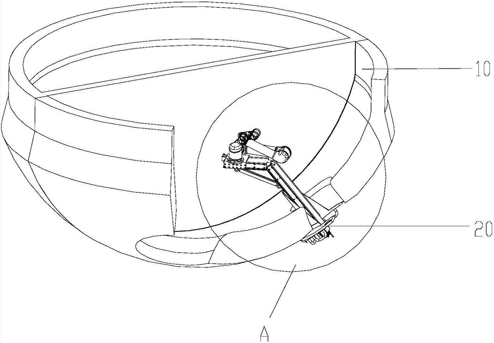
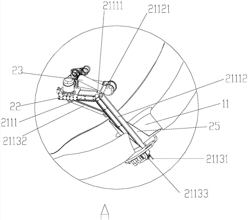
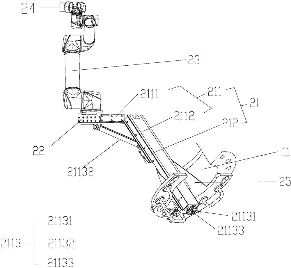
[0040] Such as Figure 1-5 As shown, this embodiment provides a video inspection device for the surface of the steam generator water chamber of a nuclear power plant, which is used to detect the contact surface of the surfacing layer in the steam generator water chamber 10 of the nuclear power plant. The video inspection device 20 consists of the The manhole 11 part of the steam generator water chamber 10 extends into the inside of the steam generator water chamber 10, which includes a positioning support frame 21, a slide block 22 arranged on the positioning support frame 21, and the slide block 22 A manipulator fixedly connected, a camera 24 arranged at the end of the manipulator, a manhole flange 25 and a locking mechanism for locking the slider 22 on the top of the positioning support frame 21 (not shown, the locking mechanism can b...


PUM


Abstract

The invention discloses a nuclear power plant steam generator water chamber inner surface video inspection device, which is used for detecting a surfacing layer contact surface in a nuclear power plant steam generator water chamber. The video inspection device consists of a positioning support frame, a sliding block disposed on the positioning support frame, a mechanical arm fixedly connected to the sliding block, a video camera disposed at the end of the mechanical arm, a manhole flange plate and a locking mechanism for locking the sliding block at the top of the positioning support frame. The mechanical arm is a six-degree-of-freedom mechanical arm, the video inspection device also includes absolute value encoders arranged at all articulation points of the six-degree-of-freedom mechanical arm, and a control system in communication connection with the absolute value encoders and the six-degree-of-freedom mechanical arm respectively, the absolute value encoders are used for reading themechanical arm included angles between two adjacent mechanical arms of the six-degree-of-freedom mechanical arm, and the video camera is in signal connection with the control system. The video inspection device provided by the invention can select any observation angle and can meet high standard definition requirement, and also can achieve real-time feedback of scanning coordinates.

Description

technical field [0001] The invention belongs to the technical field of nuclear power detection, and in particular relates to a video inspection device for the surface of a water chamber of a steam generator in a nuclear power plant. Background technique [0002] The steam generator (SG, Steam Generator) is the key equipment in the primary circuit system of the nuclear power plant. One side of it is a hemispherical head, which is divided into two approximately 1 / 4 spherical water chambers by the middle partition. There are several Thousands of tube holes, the two ends of the U-shaped heat transfer tube are expanded in the tube holes, so that the water chambers on both sides are connected. There are manholes and primary circuit pipe joints at the lower side of the water chamber. The working conditions on the surface of the SG water chamber are very harsh. Under the environment of high temperature, high pressure and high radiation for a long time, opening defects such as cracks...

Claims


Application Information

Patent Timeline
Patent Type & Authority Applications(China)
IPC IPC(8): G01N21/88G01N21/90B25J18/00
CPCG01N21/8806G01N21/8851G01N21/90G01N21/9009G01N21/9072B25J18/00G01N2021/8893G01N2021/8861G01N2021/9063
Inventor 王金龙徐达梁曾晨明石磊眭霄翔张红星高建民刘步良严志刚张伟
Owner CGNPC INSPECTION TECH
Learn More