
Eyeball tracking head-mounted display system

A head-mounted display and eye tracking technology, which is applied in the fields of eye testing equipment, medical science, optics, etc., can solve the problems of no nearsighted or farsighted lenses, inconvenient use, inconvenience, etc., to achieve convenient use and cost saving , the degree of precision effect

Pending Publication Date: 2018-04-27
WUHAN ZHIPU TIANCHUANG TECH CO LTD
View PDF8 Cites 4 Cited by
  • Summary
  • Abstract
  • Description
  • Claims
  • Application Information

AI Technical Summary

Problems solved by technology

[0003] However, the existing eye tracker does not have myopia or hyperopia lenses, and it is very inconvenient for myopic or hyperopic people to use the glasses-type eye tracker
Even if the myopia or hyperopia lens is installed on the eye tracker, because the degree of the lens cannot be adjusted, when people with different degrees come to use it, it is very inconvenient to reinstall the appropriate lens

Method used


Image

  • Eyeball tracking head-mounted display system
  • Eyeball tracking head-mounted display system
  • Eyeball tracking head-mounted display system

Examples


Embodiment Construction

[0024] The present invention will be further described in detail below with reference to the accompanying drawings, so that those skilled in the art can implement it with reference to the text of the description.

[0025] In the description of the present invention, the terms "horizontal", "vertical", "upper", "lower", "front", "rear", "left", "right", "vertical", "horizontal", " The orientation or positional relationship indicated by "top", "bottom", "inner", "outer", etc. is based on the orientation or positional relationship shown in the drawings, and is only for the convenience of describing the present invention and simplifying the description, and does not indicate or imply The device or element referred to must have a specific orientation, be constructed and operated in a specific orientation, and therefore cannot be understood as a limitation of the present invention.

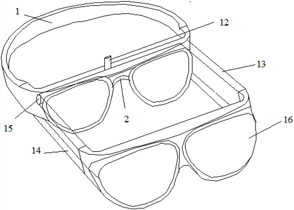
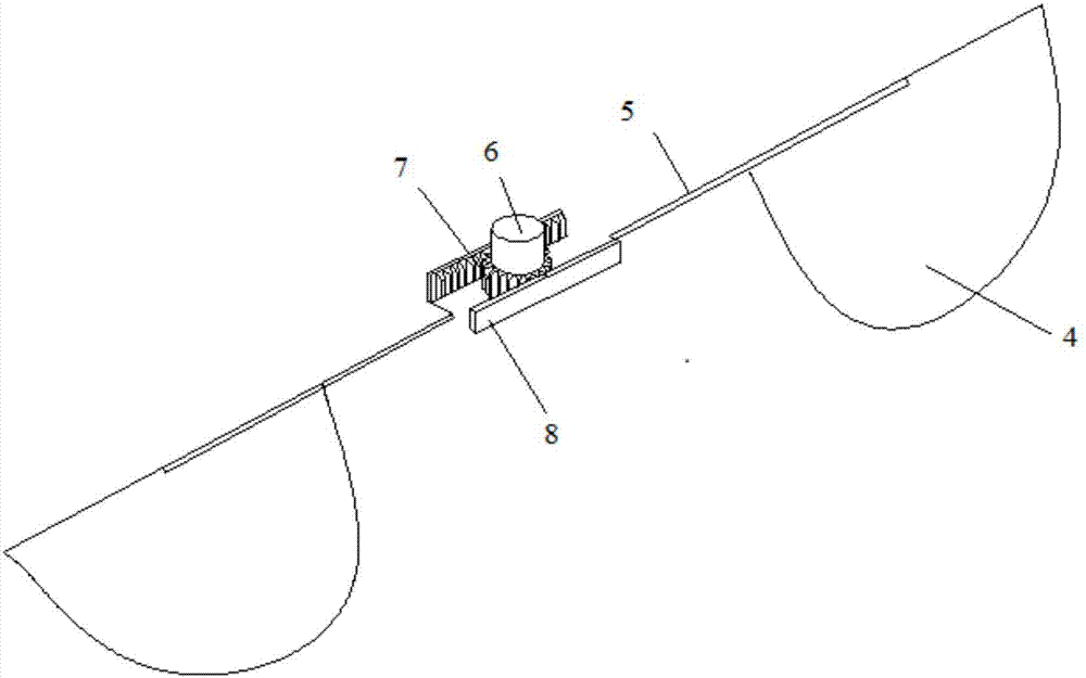
[0026] Such as Figure 1-5 As shown, the present invention provides an eye-tracking head-mounted display...


PUM


Abstract

The invention discloses an eyeball tracking head-mounted display system which includes a head shield, an inner lens frame, a pair of VR glasses, a rotating shaft, a pair of inner lenses, an adjustingdevice, and a rotary rod. The inner lens frame is fixed to the front end of the head shield, is shaped as a closed shell with a hollow inside, and is internally provided with an eye tracker. A see-through cover which can be opened and closed is arranged on the upper end face of the inner lens frame. The pair of VR glasses is fixed in parallel to the front end of the inner lens frame through a pairof first telescopic rods which can stretch out and draw back horizontally. The rotating shaft is horizontally and rotationally built in the front end of the head shield. The first telescopic rods arevertically and fixedly connected with the two ends of the rotating shaft. The other ends, away from the rotating shaft, of the first telescopic rods are hinged to the VR glasses. The pair of inner lenses is embedded into the inner lens frame. The rotary rod is vertically and rotationally arranged in the middle of the inner lens frame, and the lower end of the rotary rod is connected with a gear.The eyeball tracking head-mounted display system of the invention has the advantages of simple structure, convenience of use and adjustable degree, and can be widely applied to the technical field ofglass type eye trackers.

Description

Technical field [0001] The invention relates to the technical field of eye trackers. More specifically, the present invention relates to an eye-tracking head-mounted display system. Background technique [0002] Eye trackers are used to record the characteristics of human eye movement when processing visual information, and are used in many fields. For example, install an eye tracker in a car to record the driver’s eye movements, so as to provide an objective basis for car driving research; another example is to allow athletes to wear eye trackers to record their training during sports training. Eye movement data to understand the attention of athletes, so as to develop some training methods to improve the training effect of athletes. [0003] However, the existing eye tracker does not have myopic or hyperopic lenses, and it is very inconvenient for the near-sighted person or the far-sighted person to use the glasses-type eye tracker. Even if a nearsighted or hyperopic lens is i...

Claims


Application Information

Patent Timeline
Patent Type & Authority Applications(China)
IPC IPC(8): G02B27/01G02B27/00A61B3/113
CPCA61B3/113G02B27/0093G02B27/0172G02B27/0176
Inventor 曾瑜
Owner WUHAN ZHIPU TIANCHUANG TECH CO LTD
Learn More