
Programmable Clock Divider

A clock frequency divider and clock technology, applied in pulse counters, counting chain pulse counters, automatic power control, etc., can solve problems such as reducing power consumption

Active Publication Date: 2018-04-27
STMICROELECTRONICS SRL
View PDF12 Cites 0 Cited by
  • Summary
  • Abstract
  • Description
  • Claims
  • Application Information

AI Technical Summary

Problems solved by technology

For example, a slower clock may be required for a particular subblock to reduce power consumption

Method used


Image

  • Programmable Clock Divider
  • Programmable Clock Divider
  • Programmable Clock Divider

Examples


Embodiment Construction

[0015] The making and using of the presently preferred embodiments are discussed in detail below. It should be appreciated, however, that the present invention provides many applicable inventive concepts that can be embodied in a wide variety of specific contexts. The specific embodiments discussed are merely illustrative of specific ways to make and use the invention, and do not limit the scope of the invention.

[0016] The invention will be described with respect to the preferred embodiment in a specific context, with a high speed programmable clock divider having a duty cycle approaching fifty percent in various configurations. Embodiments of the invention may also be implemented in other configurations and using other digital techniques known in the art.

[0017] In an embodiment of the invention, the programmable clock divider is configured to generate the output clock based on dividing the input clock by a programmable integer which may have n bits. The programmable c...


PUM


Abstract

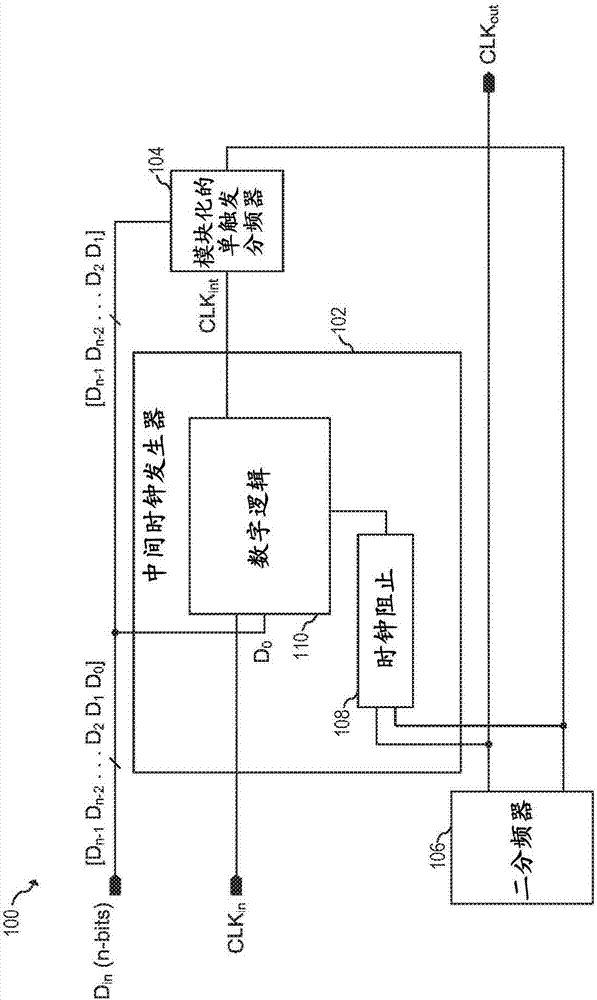
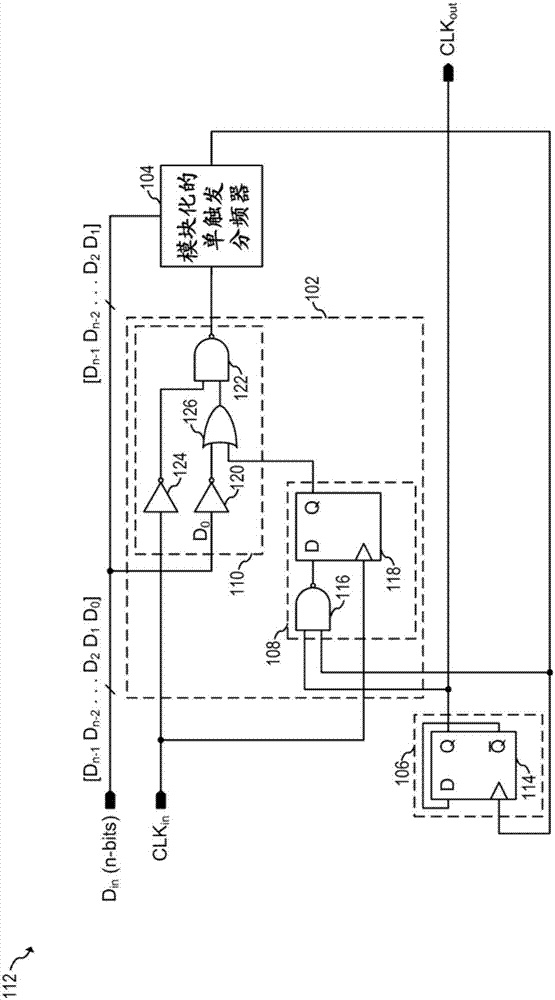
In accordance with an embodiment, a circuit includes an input clock terminal, an output clock terminal, a first input data terminal, and a set of input data terminals having a number of terminals. A divide-by-two block is coupled to the output clock terminal. A modular one-shot clock divider is coupled between the input clock terminal and the divide-by-two block. The modular one-shot clock divideris further coupled to the set of input data terminals. An intermediate clock generation block is coupled between the input clock terminal and the modular one-shot clock divider. The intermediate clock generation block includes a first digital logic block coupled between the input clock terminal and the modular one-shot clock divider. The first digital logic block is further coupled to the first input data terminal, and a clock-blocking block is coupled between the divide-by-two block and the first digital logic block.

Description

technical field [0001] The present disclosure relates generally to electronic devices, and more particularly to programmable clock dividers. Background technique [0002] Electronic devices are pervasive in many applications from computers to automobiles. Many digital circuits in electronic equipment operate with clock signals. The clocking requirements of particular circuits within a system may differ from each other for various reasons. For example, a slower clock may be required for a particular sub-block to reduce power consumption. A common technique generally used to provide appropriate clocks to each circuit in the system is to generate a sub-clock from a first clock, where the sub-clock may have a different clock frequency than the first clock. [0003] A common technique for generating a slow clock from a fast clock is to use a prescaler circuit. A prescaler circuit (also called a clock divider) is an electronic circuit configured to receive an input clock and g...

Claims


Application Information

Patent Timeline
IPC IPC(8): H03K23/00
CPCH03K23/00H03K19/20H03K21/10H03K23/70H03K21/00H03K23/667H03K23/68H03L7/1974
Inventor N·古普塔J·N·蒂瓦里
Owner STMICROELECTRONICS SRL
Learn More