Water conservancy valve surface cleaning device

A surface cleaning and valve technology, applied in the direction of cleaning methods using tools, cleaning methods and utensils, and cleaning methods using liquids, etc., can solve problems such as low work efficiency and poor cleaning effect.

Inactive Publication Date: 2018-05-01
贵乘彬
View PDF5 Cites 8 Cited by
  • Summary
  • Abstract
  • Description
  • Claims
  • Application Information

AI Technical Summary

Problems solved by technology

[0005] In order to overcome the shortcomings of low work efficiency and poor cleaning effect when manually cleaning the surface of water conservancy valves with a mop, the technical problem to be solved by the present invention is to provide a surface cleaning device for water conservancy valves with high working efficiency and good cleaning effect

Method used


Image

  • Water conservancy valve surface cleaning device
  • Water conservancy valve surface cleaning device
  • Water conservancy valve surface cleaning device

Examples


Embodiment 1

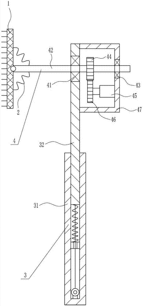
[0028] A water conservancy valve surface cleaning equipment, such as Figure 1-4 Shown, comprise hairbrush 1, the first spring 2, elevating device 3 and brushing device 4, and elevating device 3 is equipped with brushing device 4, is connected with first spring 2 and hairbrush 1 on the brushing device 4, and hairbrush 1 It is connected with the first spring 2, and the brush 1 is in the shape of a net.

Embodiment 2

[0030] A water conservancy valve surface cleaning equipment, such as Figure 1-4 Shown, comprise hairbrush 1, the first spring 2, elevating device 3 and brushing device 4, and elevating device 3 is equipped with brushing device 4, is connected with first spring 2 and hairbrush 1 on the brushing device 4, and hairbrush 1 It is connected with the first spring 2, and the brush 1 is in the shape of a net.

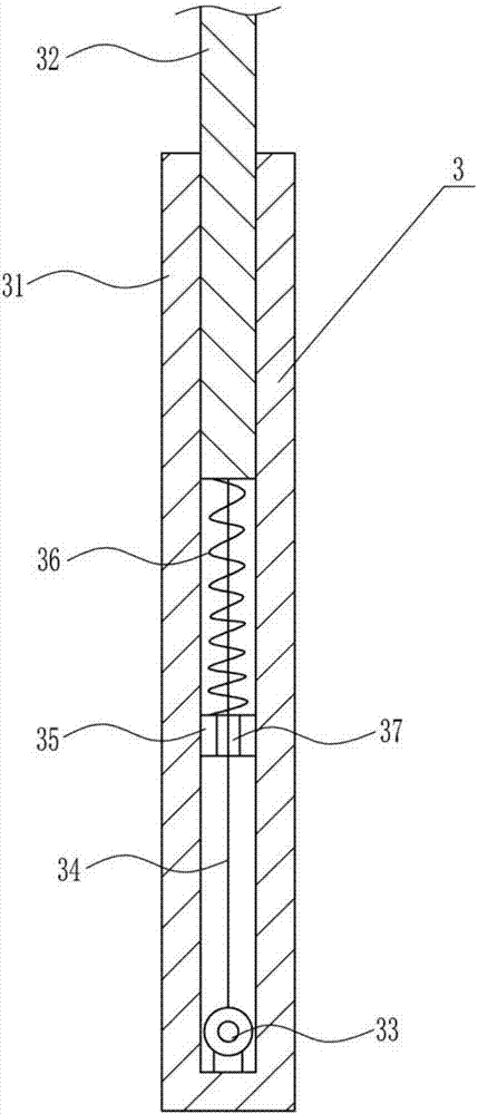
[0031]Lifting device 3 comprises outer telescopic rod 31, pole 32, electric reel 33, the first stay cord 34, connecting block 35 and second spring 36, and the inner movable type of outer telescopic rod 31 is provided with pole 32, and outer telescopic An electric reel 33 is installed at the inner bottom of the bar 31, and the first stay cord 34 is wound around the electric reel 33, and the inner middle part of the outer telescopic rod 31 is horizontally connected with a connection block 35, and the top of the connection block 35 has a through hole 37. The bottom end of the rod...

Embodiment 3

[0033] A water conservancy valve surface cleaning equipment, such as Figure 1-4 Shown, comprise hairbrush 1, the first spring 2, elevating device 3 and brushing device 4, and elevating device 3 is equipped with brushing device 4, is connected with first spring 2 and hairbrush 1 on the brushing device 4, and hairbrush 1 It is connected with the first spring 2, and the brush 1 is in the shape of a net.

[0034] Lifting device 3 comprises outer telescopic rod 31, pole 32, electric reel 33, the first stay cord 34, connecting block 35 and second spring 36, and the inner movable type of outer telescopic rod 31 is provided with pole 32, and outer telescopic An electric reel 33 is installed at the inner bottom of the bar 31, and the first stay cord 34 is wound around the electric reel 33, and the inner middle part of the outer telescopic rod 31 is horizontally connected with a connection block 35, and the top of the connection block 35 has a through hole 37. The bottom end of the ro...


PUM


Abstract

The invention relates to a cleaning device, in particular to a water conservancy valve surface cleaning device. The water conservancy valve surface cleaning device is high in working efficiency and good in cleaning effect. The water conservancy valve surface cleaning device comprises a brush and the like; a brushing device is arranged on a lifting device; and a first spring and the brush are connected to the brushing device, the brush is connected with the first spring, and the brush is in a net shape. Through the cooperation of the lifting device and the brushing device, the brush can rotatevertically while moving up and down, the surface of the water conservancy valve is brushed, and a water spraying device is used for spraying water, so that the surface of the water conservancy valve can be cleaned more completely.

Description

technical field [0001] The invention relates to a cleaning device, in particular to a cleaning device for the surface of a water conservancy valve. Background technique [0002] The word water conservancy was first seen in the chapter "Filial Piety and Caution for People" in "Lu Shi Chunqiu" published at the end of the Warring States period, but the "water conservancy" it mentioned refers to the benefit of fishing. From about 104 BC to 91 BC, Sima Qian, a historian of the Western Han Dynasty, wrote "Historical Records", among which "Hequshu" (see "Historical Records·Hequshu") is China's first general history of water conservancy. After describing a series of historical facts of river control and flood control, canal opening and navigation, and water diversion and irrigation during the historical period from Yu's water control to the Yellow River Huzi blockage by Emperor Wu of the Han Dynasty, the book sighed: "Water is a good or bad thing", and pointed out "Since then, thos...

Claims


Application Information

Patent Timeline
IPC IPC(8): B08B1/00B08B1/04B08B3/02
CPCB08B3/02B08B2203/02B08B1/30B08B1/32B08B1/12
Inventor 贵乘彬周登成曾钰婷
Owner 贵乘彬
Why Eureka
Try Eureka