A Dense Array High-Speed ​​Micro-Stamping Equipment

A micro-stamping and equipment technology, applied in metal processing equipment, manufacturing tools, punching tools, etc., can solve the problems of complex micro-stamping dies, limited stamping accuracy of stamping machines, complex stamping dies, etc., to reduce complexity and production costs, Improve production efficiency and ensure the effect of stamping quality

Active Publication Date: 2019-03-26
SHANDONG UNIV OF SCI & TECH
View PDF11 Cites 0 Cited by
  • Summary
  • Abstract
  • Description
  • Claims
  • Application Information

AI Technical Summary

Problems solved by technology

The disadvantages of the above-mentioned punching device or punching machine are: a single punching head is used for processing, and its efficiency is low
[0004] In addition, most of the existing stamping devices have the following problems: (1), the stamping accuracy of the stamping machine is limited, including the stamping position, the size of the stamping force and the stamping speed cannot be well controlled; (2), the stamping equipment The design and manufacture are more complicated and the cost is relatively high; (3), with the complexity of micro-stamping parts, the micro-stamping dies will become more and more complicated, which will lead to more and more complex design and manufacture of stamping parts of stamping equipment. The increase in the number will make the stamping die more complicated, which will make the design and manufacture more difficult; (4), with the increase in the demand for micro-parts, the requirements for its production cost, efficiency and forming quality are more stringent, as shown in Desire to mass-produce miniature parts at lower cost, higher quality and productivity

Method used


Image

  • A Dense Array High-Speed ​​Micro-Stamping Equipment
  • A Dense Array High-Speed ​​Micro-Stamping Equipment
  • A Dense Array High-Speed ​​Micro-Stamping Equipment

Examples


Embodiment 1

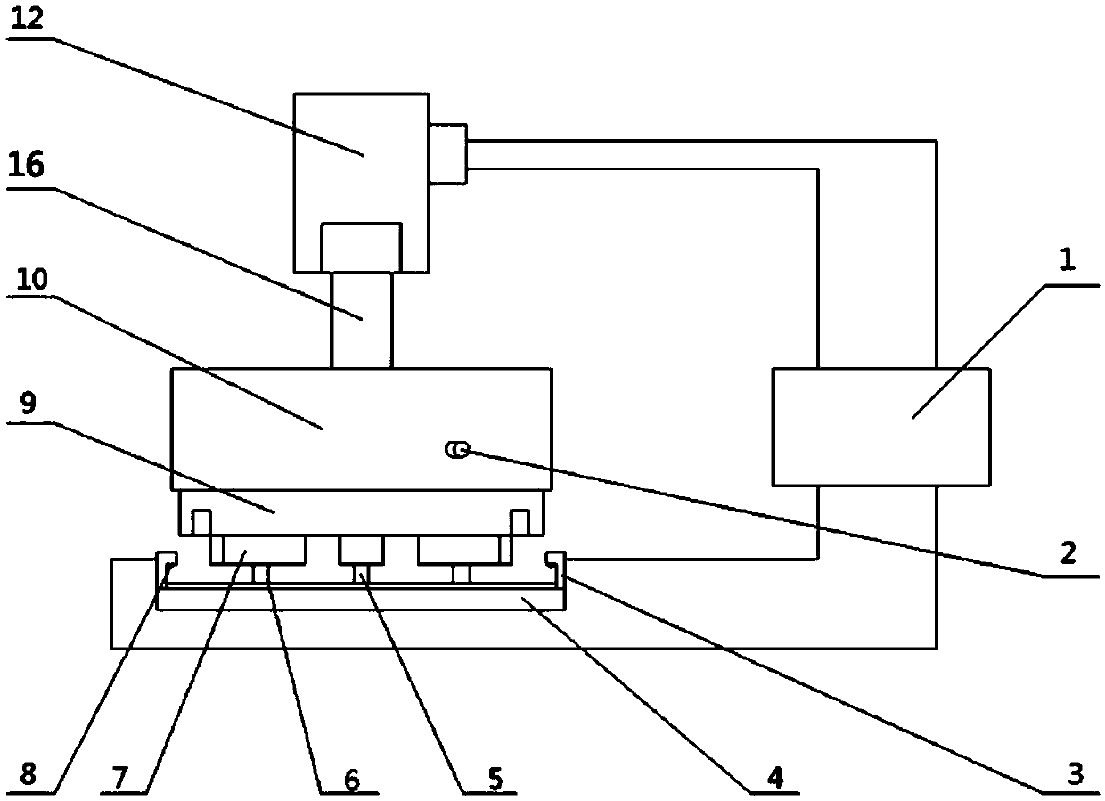
[0035] Such as Figure 1 to Figure 7 As shown, a dense array of high-speed micro-stamping equipment includes a punch clamping and positioning device, a stamping parameter adjustment device, a workpiece clamping and positioning device, and a lifting drive device that drives the punch clamping and positioning device to perform lifting movements.

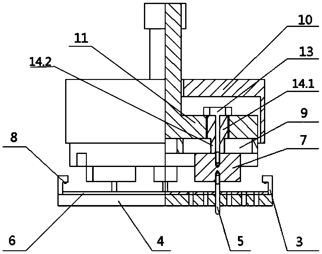
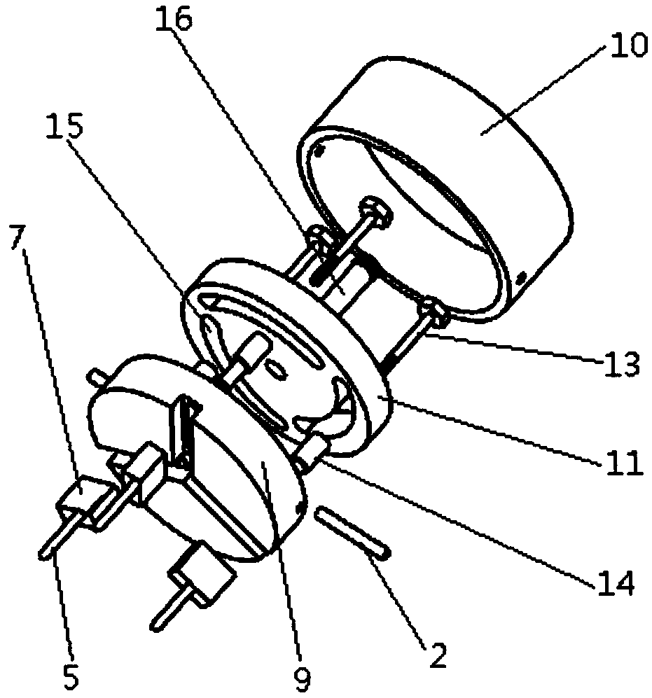
[0036] Such as Figure 1 to Figure 5 As shown, the punch clamping and positioning device includes an adjusting plate 11 , a track plate 9 , a stepped shaft 14 , a punch seat 7 and a positioning cover 10 . The positioning cover 10 is set on the outside of the adjusting disc 11 and the track disc 9, the positioning cover 10 is fixedly connected with the track disc 9 through the pin 2, and the positioning cover 10 and the track disc 9 are interference fit. The positioning cover 10 and the adjusting disc 11 are separated from each other.

[0037] There are three stepped shafts 14, three punch seats 7, and a punch punch 5 is respectively ...

Embodiment 2

[0048] The structure of this embodiment is the same as that of Embodiment 1, the only difference lies in the control aspect, specifically, when the micro stamping equipment in the present invention is used for processing such as Figure 8 For the workpiece to be processed as shown, the control process of embodiment 2 is more than that of embodiment 1, with one more control process for the conversion of punching position.

[0049] Such as Figure 8 As shown, the workpiece to be processed is compared with Figure 6 For the workpiece to be processed, there are three more rows of stamping holes 19 that need to be stamped. Therefore, the micro stamping equipment of the present invention is used for such as Figure 8 When the workpiece to be processed shown is processed, with the rotation of the adjustment disc 11, the punch punch 5 is first driven to move horizontally along the direction A. When the stepped shaft 14 moves to the limit position of the motion track groove 18 or when...

Embodiment 3

[0051] The structure of this embodiment is the same as that of Embodiment 1, the only difference lies in the control aspect, specifically, when the micro stamping equipment in the present invention is used for processing such as Figure 9 For the workpiece to be processed as shown, the control process of embodiment 3 has one more control process for punching position conversion than the control process of embodiment 1.

[0052] Such as Figure 9 As shown, the workpiece to be processed is compared with Figure 8 For the workpiece to be processed, there are three more rows of stamping holes 19 that need to be stamped. Therefore, the micro stamping equipment of the present invention is used for such as Figure 9 When the workpiece to be processed shown is processed, with the rotation of the adjustment disc 11, the punch punch 5 is first driven to move horizontally along the direction A. When the stepped shaft 14 moves to the limit position of the motion track groove 18 or when t...


PUM


Abstract

The invention discloses a dense array high-speed micro stamping equipment, which belongs to the field of precision machinery manufacturing, and comprises a punch clamping and positioning device, which includes an adjusting disc, a track disc, a stepped shaft, a punch seat and a positioning cover shell; there are multiple stepped shafts, the number of punch seats is the same as that of the stepped shafts, and a punch punch is provided at the bottom of each punch seat, and each stepped shaft includes a connected upper shaft section and a lower shaft section , the adjusting disk is provided with an arc-shaped groove matching the upper shaft section along its circumference, and the track disk is provided with a motion track groove matching the lower shaft section along its radial direction, and the distribution of the motion track groove is consistent with the The arrangement of the array stamping holes to be processed on the workpiece is consistent, and the micro stamping equipment also includes a rotary driving part that drives the rotation of the adjustment disc. The invention realizes that only a few punches and punches can be used to replace the complex stamping device in the prior art that needs to be provided with multiple punches and punches to produce workpieces to be processed, and the production efficiency is improved.

Description

technical field [0001] The invention belongs to the technical field of precision machinery manufacturing, and relates to stamping equipment, in particular to a dense array high-speed micro stamping equipment. Background technique [0002] The micro stamping device is suitable for stamping parts with small size and high precision requirements. At present, it has been widely used in industrial fields such as microelectronic integrated circuits, biomedicine, printing, dyeing and textiles. With the increasing demand for micro-stamping products, more and more attention is paid to the process of micro-stamping. [0003] Existing punching devices or punching machines all include a frame, a bottom mold fixed on the frame, an upper template that moves up and down relative to the frame, and a punch corresponding to the bottom mold is fixed on the upper template. , the upper template is connected with the oil cylinder or cylinder that drives it to move up and down. Driven by the oil ...

Claims


Application Information

Patent Timeline
Patent Type & Authority Patents(China)
IPC IPC(8): B21D28/26B21D28/34
CPCB21D28/26B21D28/34
Inventor 苏春建孔伟进袁凤如杨龙允梅林强曹高华赵泽轩董艺璇王清
Owner SHANDONG UNIV OF SCI & TECH
Why Eureka
Try Eureka