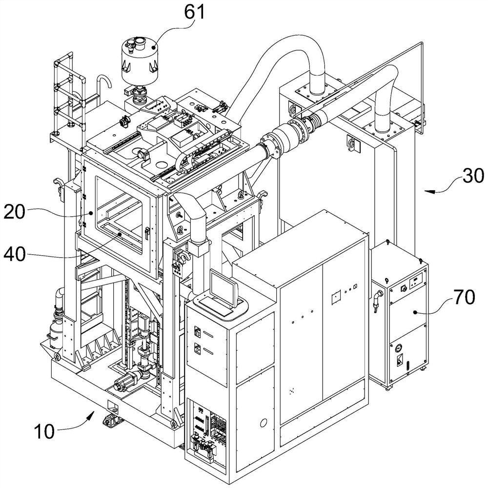
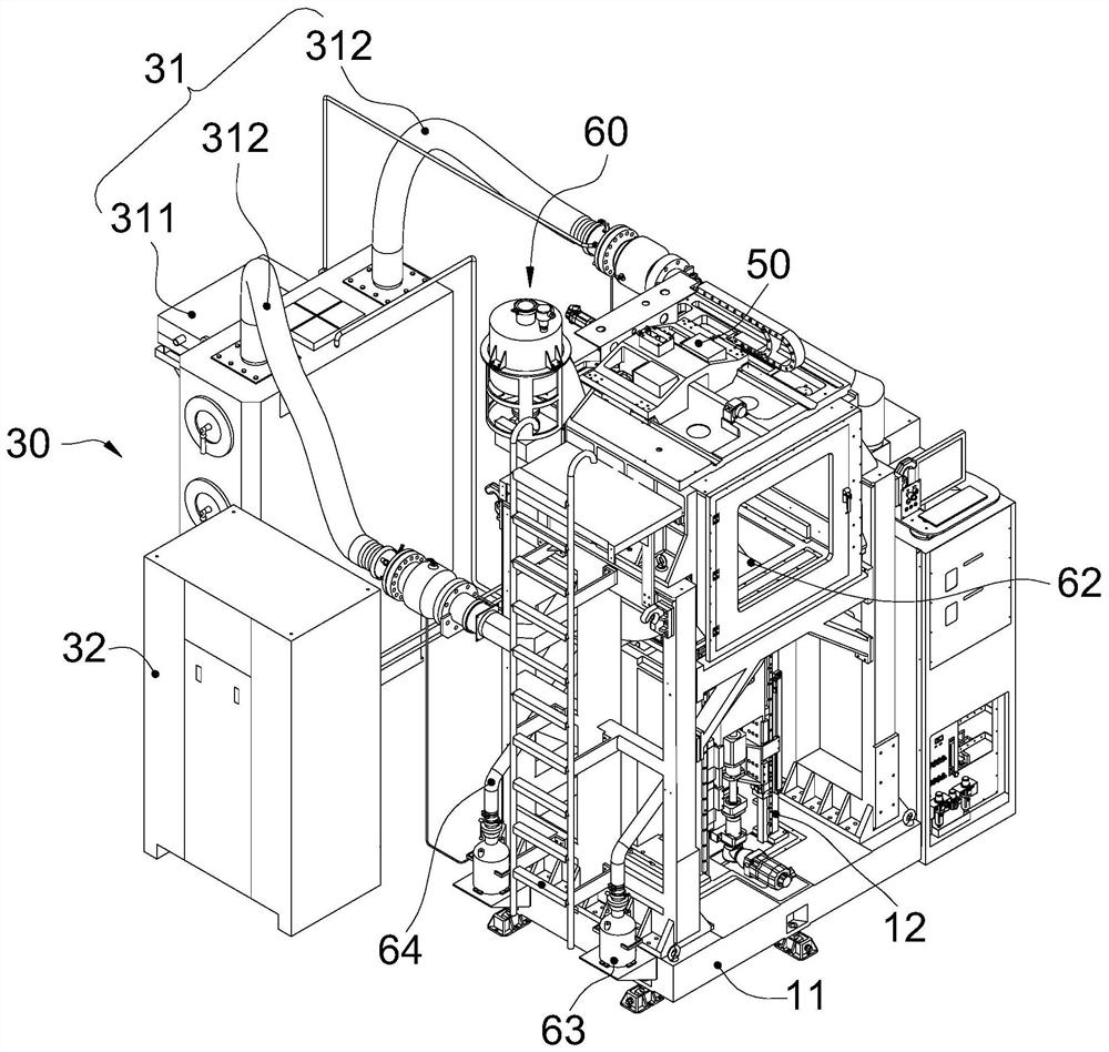
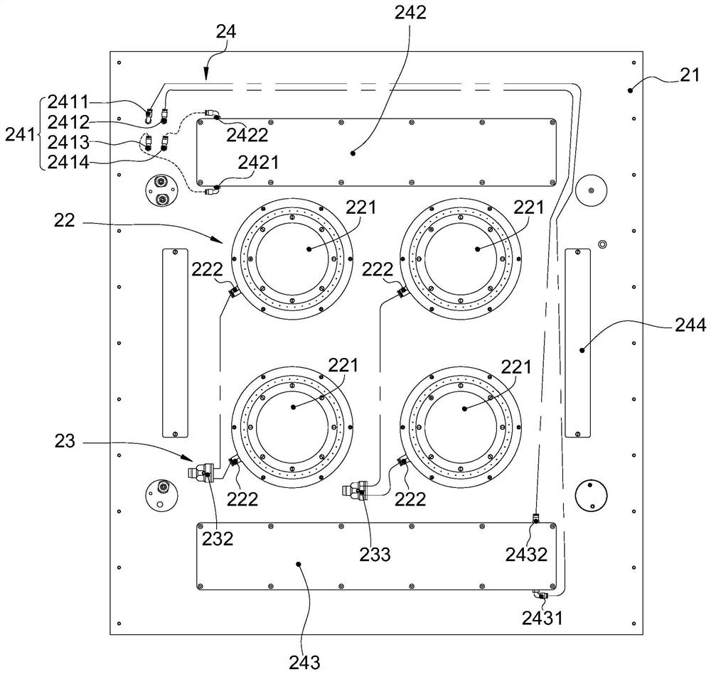
A laser 3d printing device

A 3D printing and equipment technology, which is applied in the field of additive manufacturing, can solve the problems of easy change of stacked shape, reflection, adhesion of formed particles, etc., and achieve the effect of avoiding the waste of laser energy

Inactive Publication Date: 2021-03-26
湖南尚亿达科技有限责任公司
View PDF6 Cites 0 Cited by
  • Summary
  • Abstract
  • Description
  • Claims
  • Application Information

AI Technical Summary

Problems solved by technology

[0011] In view of the above-mentioned problems existing in the prior art, the object of the present invention is to provide a laser 3D printing equipment, which breaks through the limitation of the size of the internal station of the laser melting molding in the prior art, and solves the problems in the prior art. Laser focusing can only be locally heated, so that the pre-distributed molding powder is prone to change in the shape of the accumulation under the condition of uneven heating, which affects the shape of the final molded part, resulting in a problem of lower product yield. And it solves the problem that the traditional injection of protective gas tends to cause small-radius molding particles to adhere to the lens, which easily makes the laser diffuse or reflect, and weakens the energy of the laser.

Method used


Image

  • A laser 3d printing device
  • A laser 3d printing device
  • A laser 3d printing device

Examples


Embodiment Construction

[0036] DETAILED DESCRIPTION OF THE PREFERRED EMBODIMENTS It should be understood that the specific embodiments described herein are intended to illustrate and explain the present invention and is not intended to limit the invention.

[0037] For ease of description, space relative terms can be used here, such as "above ...", "in ... above", "in ... upper surface", "above", etc., used to describe as in the figure A device or feature of a device or a spatial position relationship between other devices or features. It should be understood that space relative terms is intended to include different orientations in use or operation in addition to the orientation of the device in the figure. For example, if the device in the drawing is invert, it will be positioned as "above other devices or" above "or" above other devices or constructs "or" below "or" in other devices "or" Other devices or under construction. " Thus, exemplary terms "above" may include "in ... above" and "in ... below"....


PUM


Abstract

The invention relates to a laser 3D printing device, which includes a frame part, a forming part fixed on the frame part, a gas protection part, a laser scanning part, a powder spreading part, and a preheating part which can preheat the formed powder, The forming part is a relatively sealed internal cavity surrounded by a plurality of components fixed to the frame part, the gas protection part is placed outside the frame part, and is in cyclic communication with the forming part, and the laser scanning part Movably fixed along the outer side of the molding part, the preheating part is fixed on the opposite side of the molding part, and is telescopically fixed inside the frame part, and the powder spreading part extends into the inside of the molding part Cavity fixation. It can effectively avoid the waste of laser energy caused by the diffusion or reflection of the laser during the molding process, and the problem of low product yield due to the easy change of the shape of the uneven accumulation of the molding powder due to heating.

Description

Technical field [0001] The present invention belongs to the field of additive manufacturing, and more particularly to a laser 3D printing apparatus that melts / melts / melts the powder by laser using a laser using a laser. Background technique [0002] Laser 3D prints as a additive manufacturing technology, with high printing accuracy and printing speed, wide materials are applicable, suitable for processing molding of multiple metal or non-metallic materials. Laser 3D printing is a technique for directly producing parts using CAD generated, the main principle is to use an infrared laser as an energy source. The molding material used is mostly powder material. When processing, first preheat the powder to slightly lower than The temperature of the melting point is then flatten under the scraping stick; the laser beam is selectively sintered according to the layered cross-section information under computer control, and then the next layer is sintered after completion. If you remov...

Claims


Application Information

Patent Timeline
Patent Type & Authority Patents(China)
IPC IPC(8): B22F3/105B33Y30/00
CPCB33Y30/00B22F10/00B22F12/90B22F10/32B22F12/13B22F10/20Y02P10/25
Inventor 席义清
Owner 湖南尚亿达科技有限责任公司
Why Eureka
Try Eureka