
Plastic extrusion device

An extrusion device and plastic technology, applied in the field of plastic processing accessories, can solve the problems of high use limitations, inability to mix materials, poor stability, etc., and achieve the effects of improving stability, reducing use limitations, and reducing waste.

Inactive Publication Date: 2018-05-01
ZHENGZHOU LONGWEI ELECTRONICS TECH CO LTD
View PDF0 Cites 4 Cited by
  • Summary
  • Abstract
  • Description
  • Claims
  • Application Information

AI Technical Summary

Problems solved by technology

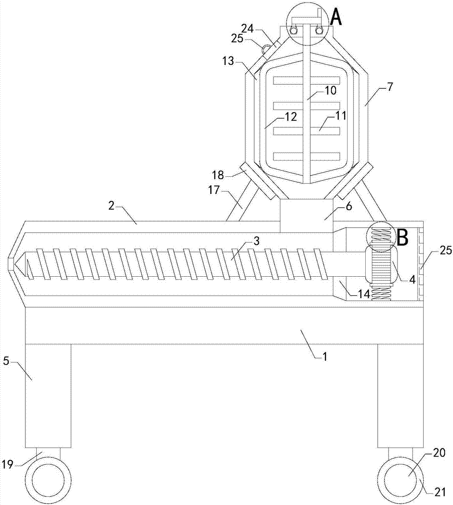
[0002] As we all know, a plastic extrusion device is an accessory device used in the plastic processing process to fully plasticize and evenly mix materials and extrude them. It has been widely used in the field of plastic processing; existing The plastic extrusion device includes a workbench, a workbox, a screw and a motor. There are four sets of support columns on the left front, left rear, right front and right rear of the bottom of the workbench. The workbox is placed on the workbench and placed on the There is a working cavity in the working box, the screw is located in the working box, and the right end of the screw passes through the right side wall of the working box and connects with the central area of ​​the left side wall of the motor. The central area of ​​the left side wall is respectively provided with a material inlet and a material outlet, and both the material inlet and the material outlet are connected to the working chamber; when the existing plastic extrusion device is used, the motor is turned on to make the screw rotate in the working box, The material is poured into the working box through the feed port, and the pressure and shear force generated by the rotation of the screw make the material fully plasticized and uniformly mixed, and extruded through the discharge port; the existing plastic extrusion device is in use It is found that it can only add materials to the work box at any time, and cannot temporarily store materials; and it can only add mixed materials, and cannot directly mix materials, which has high limitations in use; at the same time, the position of its motor cannot be fixed. resulting in poor stability

Method used


Image

  • Plastic extrusion device
  • Plastic extrusion device
  • Plastic extrusion device

Examples


Embodiment Construction

[0015] The specific implementation manners of the present invention will be further described in detail below in conjunction with the accompanying drawings and embodiments. The following examples are used to illustrate the present invention, but are not intended to limit the scope of the present invention.

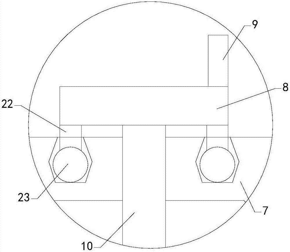
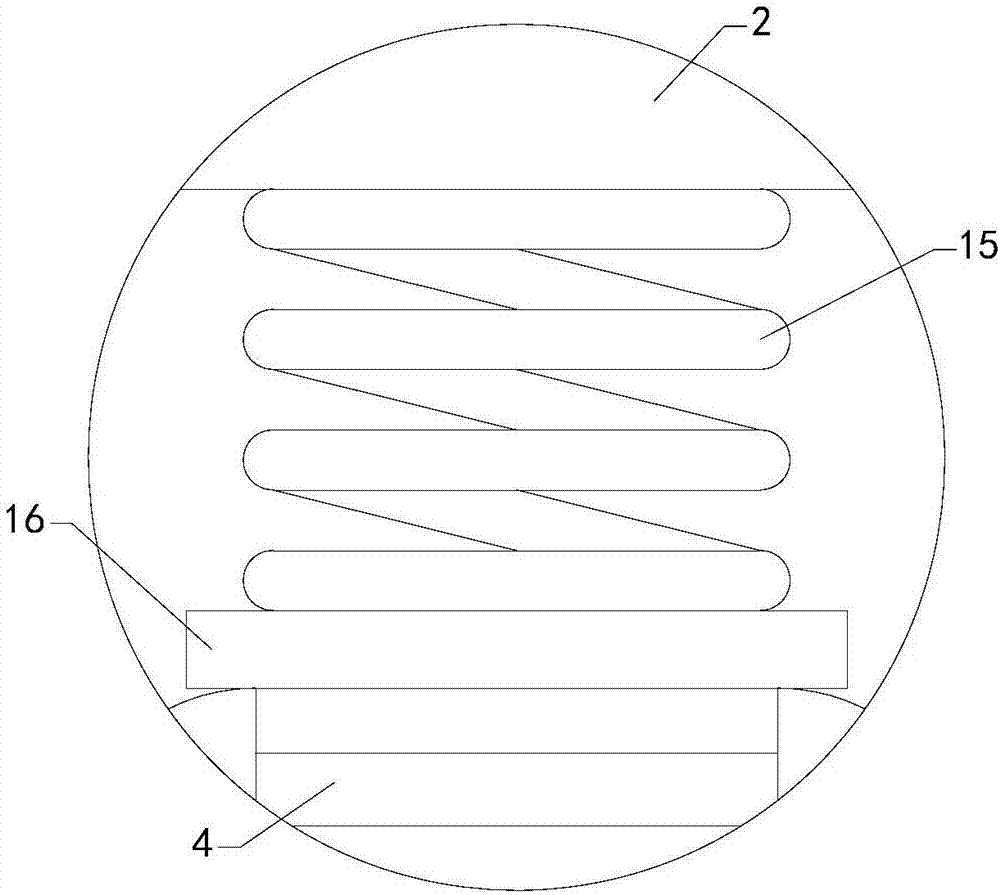
[0016] Such as Figure 1 to Figure 3 As shown, a plastic extrusion device of the present invention includes a workbench 1, a workbox 2, a screw 3 and a motor 4, and four sets of supports are respectively arranged on the left front side, the left rear side, the right front side and the right rear side of the bottom of the workbench Column 5, the work box is placed on the workbench, and a working cavity is arranged in the work box, the screw is located in the work box, and the right end of the screw passes through the right side wall of the work box to connect with the central area of ​​the left side wall of the motor, and the motor is installed in the work box On the right...


PUM


Abstract

The invention relates to the technical field of plastic processing auxiliary devices, in particular to a plastic extrusion device. Materials can be temporarily stored in the plastic extrusion device,the materials can be directly mixed, and the using limitation is reduced; meanwhile, the position of a motor can be fixed, and the stability is improved; the plastic extrusion device comprises a working table, a working box, a screw and the motor, four supporting columns are arranged at the bottom of the working table, the working box is placed on the working table, a feeding pipe is arranged at the position of a feeding opening, and a storing box is arranged at the top end of the feeding pipe; a rotary disc, a rotating handle, a transmission shaft and a set of stirring blades are further included, the rotating handle is installed on the right half zone of the top of the rotary disc, a left connecting support and a right connecting support are arranged on the transmission shaft, and the left side wall of the left connecting support and the right side wall of the right connecting support are provided with a left scraping sheet and a right scraping sheet corresponding; and a baffle, an upper fixing spring, a lower fixing spring and a stopping door are further included, and the bottom end of the upper fixing spring and the top end of the lower fixing spring are provided with an upperclamping plate and a lower clamping plate correspondingly.

Description

technical field [0001] The invention relates to the technical field of plastic processing attachments, in particular to a plastic extruding device. Background technique [0002] As we all know, a plastic extrusion device is an accessory device used in the plastic processing process to fully plasticize and evenly mix materials and extrude them. It has been widely used in the field of plastic processing; existing The plastic extrusion device includes a workbench, a workbox, a screw and a motor. There are four sets of support columns on the left front, left rear, right front and right rear of the bottom of the workbench. The workbox is placed on the workbench and placed on the There is a working cavity in the working box, the screw is located in the working box, and the right end of the screw passes through the right side wall of the working box and connects with the central area of ​​the left side wall of the motor. The central area of ​​the left side wall is respectively pro...

Claims


Application Information

Patent Timeline
IPC IPC(8): B29C47/10B29C47/38B29C47/08B29C48/395
CPCB29C48/25B29C48/252B29C48/285B29C48/287B29C48/397
Inventor 王波
Owner ZHENGZHOU LONGWEI ELECTRONICS TECH CO LTD
Learn More