Spring clamp unlocking mechanism for catapult-assisted take-off unmanned aerial vehicle

A spring clip, UAV technology, applied in the direction of launch/drag transmission, etc., can solve the problems of easy damage, breakage, etc., and achieve the effect of ensuring safe release, avoiding damage to its own structure, and improving the convenience of operation.

Pending Publication Date: 2018-05-01
BEIJING INST OF AEROSPACE TESTING TECH
View PDF3 Cites 3 Cited by
  • Summary
  • Abstract
  • Description
  • Claims
  • Application Information

AI Technical Summary

Problems solved by technology

Once the lock release mechanism fails, the plane may break after taking off
And the release mechanism itself is on the ejection trolley, which is easy to be damaged and cause malfunction under the condition of high acceleration

Method used


Image

  • Spring clamp unlocking mechanism for catapult-assisted take-off unmanned aerial vehicle

Examples


Embodiment Construction

[0009] Below in conjunction with accompanying drawing, further illustrate the present invention with example.

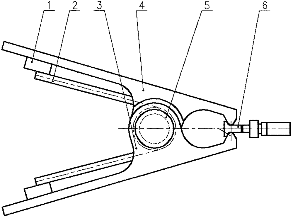
[0010] Such as figure 1 As shown, a spring clip release mechanism for a catapult-type unmanned aerial vehicle includes an adjustment block 1, a torsion spring 2, an inner clip 3, an outer clip 4, a rotating shaft 5, and a clamping rod 6.

[0011] Spring releases are used in pairs. During use, the rotating shaft 5 is fixed on the spring clip bracket, and the lower end of the bracket is fixed on the starting end of the ejection frame. Clamping bar 6 is fixed below the drone wing. Pinch the clips 3 and 4 of the spring clip to clamp the clamping rod 6 and adjust its position so that the spring clip tightens the clamping rod 6 . Adjust the gap between the spacer 1 and the clips 3, 4, thereby adjusting the deformation of the torsion spring 2, thereby adjusting the magnitude of the clamping force. The deformation and stiffness of the torsion spring, the force arm of the...


PUM


Abstract

The invention provides a spring clamp mechanism capable of adjusting and controlling unlocking force and used for the safe separation between an aircraft and a catapult carrier during the catapult-assisted take-off process of an unmanned aerial vehicle (UAV). The spring clamp mechanism comprises adjustment cushion blocks, torsion springs, an outer clamping plate, an inner clamping plate, a fixingshaft and a clamping rod, wherein the clamping rod is provided with an overload breaking groove; and the parts that the clamping rod is in contact with the inner clamping plate and the outer clampingplate are provided with tangent arc surfaces. The spring clamp mechanism has the advantages that positive pressure and frictional force between clamping contact surfaces are controlled by the pre-compression deformation of the torsion springs, and that the aircraft is separated from the carrier when forward thrust of propellers overcomes the component in the thrust direction of resultant force ofthe positive pressure and the frictional force between the clamping contact surfaces. The pre-compression deformation is adjusted through the cushion blocks so that the unlocking force is adjustable and controllable, and after overloading, the clamping rod can break automatically to achieve the effect of safe and reliable separation between the aircraft and the carrier.

Description

technical field [0001] The invention relates to a spring clip mechanism, which can adjust the release force of a clamped UAV, and is suitable for the technical field of a catapult take-off UAV. Background technique [0002] UAV catapult take-off is an advanced UAV launch method that has appeared in the world in recent years. Compared with other launch methods, it has the advantages of good safety and concealment, good economy, and good adaptability. It has become the United States and the United Kingdom. , Research hotspots in many countries in China. The research situation of the UAV locking and releasing mechanism is as follows: American Scan Eagle Superwedge adopts a rotating clamping arm mechanism, which is mainly composed of two structures of the upper and lower clamping arms connected by thread pairs, and the upper clamping arm clamps the aircraft fuselage and the wings on both sides , the lower clamping arm is fixed on the trolley. When the aircraft reaches the take...

Claims


Application Information

Patent Timeline
Patent Type & Authority Applications(China)
IPC IPC(8): B64F1/06
CPCB64F1/06
Inventor 沈冰妹李茂张佳张家仙孙凤伟王成刚张登攀宋舟航
Owner BEIJING INST OF AEROSPACE TESTING TECH
Why Eureka
Try Eureka