Tentering and heat-setting machine oven structure optimization method

A heat-setting machine and optimization method technology, applied in special data processing applications, instruments, electrical digital data processing and other directions, can solve the problems of uneven temperature distribution of the setting machine, poor fluid operation, etc. Reduce vortex strength and improve the effect of vortex structure

Active Publication Date: 2018-05-01
ZHEJIANG SCI-TECH UNIV
View PDF6 Cites 3 Cited by
  • Summary
  • Abstract
  • Description
  • Claims
  • Application Information

AI Technical Summary

Problems solved by technology

[0007] The invention provides a method for optimizing the oven structure of a stenter heat setting machine, which can effectively solve the problems of poor fluid operation during the operation of the oven and uneven temperature distribution in the setting machine during the heat setting process.

Method used


Image

  • Tentering and heat-setting machine oven structure optimization method
  • Tentering and heat-setting machine oven structure optimization method
  • Tentering and heat-setting machine oven structure optimization method

Examples


Embodiment Construction

[0042] The present invention will be described in further detail below in conjunction with the accompanying drawings.

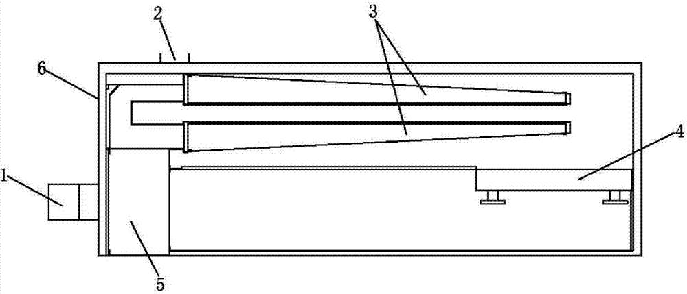
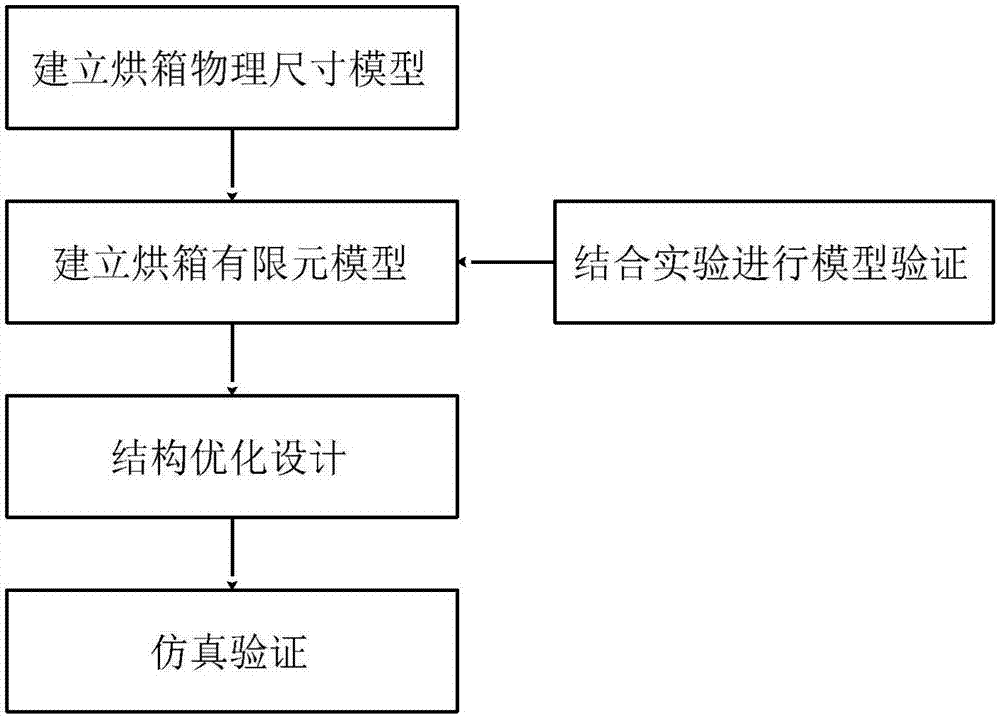
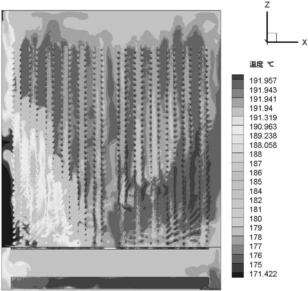
[0043] A method for optimizing the oven structure of a stenter heat setting machine, that is, by analyzing the structure of the existing oven of the setting machine, using CFD software to simulate the problems of poor fluid operation and uneven distribution of the internal temperature field during the operation of the oven, and On this basis, a new mechanism is proposed to improve the internal flow state and eliminate the unstable flow field structure, so as to solve this problem. The overall flow chart is as figure 2 as shown,

[0044] One: Build a physical size model

[0045] Based on the traditional stenter heat setting machine, a 1:1 physical size model is established. Based on the 3D model of equal size, the simulation of the internal flow field and the verification after optimization are done.

[0046] Two: Carry out finite element-based fluid simu...


PUM


Abstract

The invention discloses a tentering and heat-setting machine oven structure optimization method. Through the method, hydrodynamic performance in the operating process of a traditional setting machineoven is realized, the situation that an original structure is unreasonable and a vortex structure exists is relieved, a local flow field is optimized, vortex strength is obviously lowered, the problems that energy is excessively consumed and a fire hidden danger is generated because exhaust is unsmooth and fiber dust is prone to accumulation at the vortex structure are solved, and a basis is provided for energy-saving, environment-friendly and safe production of a setting machine.

Description

technical field [0001] The invention relates to the field of printing and dyeing heat setting machines, in particular to a method for optimizing the oven structure of a tenter heat setting machine. Background technique [0002] The so-called heat setting is the process of placing the fabric in a high temperature environment (such as 180-200°C) under tension and maintaining a certain size or shape. After heat treatment for a period of time, it is then rapidly cooled. In this process, due to the good thermoplasticity of synthetic fibers, when placed in a high-temperature environment, the rearrangement of macromolecular segments causes great changes in the microstructure and morphology of the fibers, making the changed fiber microstructures Therefore, the main function of heat setting is to give the fabric a relatively stable size and shape. [0003] Since synthetic fibers and their blended fabrics have been subjected to dry and wet heat treatment for many times in the process...

Claims


Application Information

Patent Timeline
Patent Type & Authority Applications(China)
IPC IPC(8): G06F17/50
CPCG06F30/17
Inventor 李昆航顾敏明
Owner ZHEJIANG SCI-TECH UNIV
Why Eureka
Try Eureka