Direct-cooling closed heat dissipation chassis

A chassis, direct cooling technology, applied in the direction of cooling/ventilation/heating transformation, modification using gaseous coolant, electrical components, etc., can solve the problem of low heat dissipation efficiency and achieve the effect of improving heat dissipation effect

Pending Publication Date: 2018-05-01
成都洛的高新材料技术有限公司
View PDF10 Cites 2 Cited by
  • Summary
  • Abstract
  • Description
  • Claims
  • Application Information

AI Technical Summary

Problems solved by technology

[0006] The purpose of the present invention is to provide a direct cooling airtight heat dissipation chassis, which can well solve the problem that the heat of the heat generating device needs to be conducted multiple times before it can be taken out of the chassis, resulting in low heat dissipation efficiency

Method used


Image

  • Direct-cooling closed heat dissipation chassis
  • Direct-cooling closed heat dissipation chassis
  • Direct-cooling closed heat dissipation chassis

Examples


Embodiment

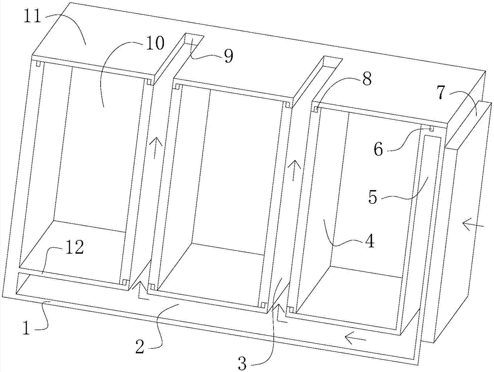
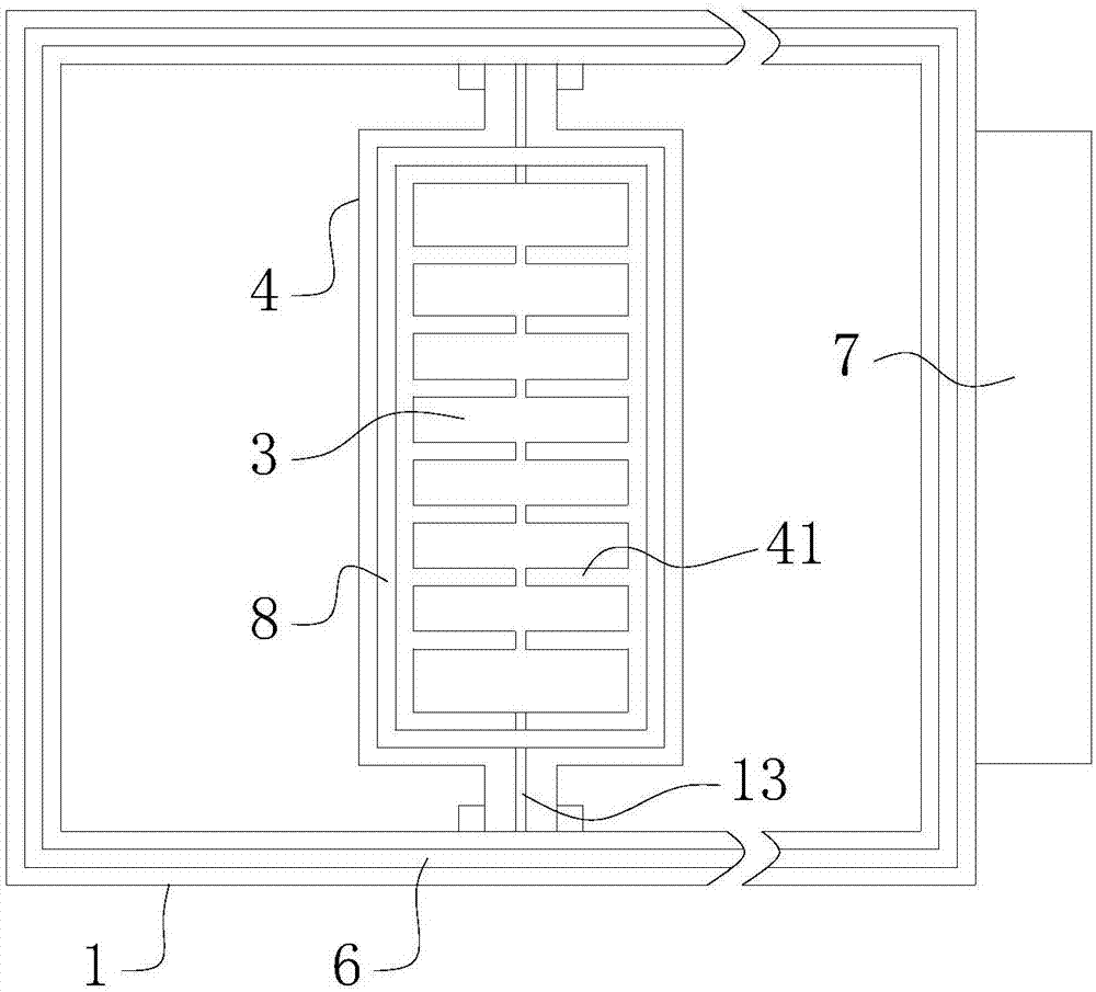
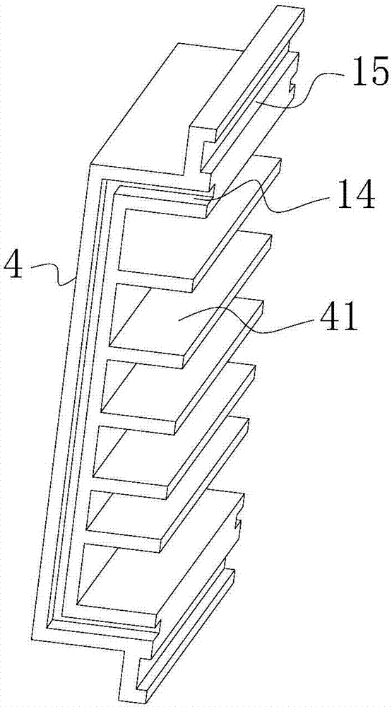
[0023] Such as Figure 1-3 As shown, the direct cooling airtight cooling cabinet provided in this embodiment includes a box body 1, a partition plate 12, a cover plate 11 and at least two cold plates 4, and the partition plate 12 divides the inner cavity of the box body 1 into an isolated cavity and a In the air inlet chamber 2, two adjacent cold plates 4 are connected back to back to form a cold plate group. A heat dissipation channel 3 is arranged between the two cold plates 4 of the cold plate group. The cold plate 4 is installed in the isolation chamber of the box body 1. The cold plate group divides the isolation chamber of the box body 1 into at least two device chambers 10, the cover plate 1 is installed on the box body to seal the device chamber 10, and the box body 1 is provided with an air inlet to connect to the fan group 7 so that the fan Group 7 sends the wind into the air inlet cavity 2, and the partition plate 12 is provided with an air duct opening connecting t...


PUM


Abstract

The invention relates to a direct-cooling closed heat dissipation chassis which comprises a box body, a partition plate, a cover plate and at least two cooling plates, wherein an inner cavity of the box body is partitioned into an isolation chamber and an air inlet chamber by virtue of the partition plate; two adjacent cooling plates are connected back to back to form a cooling plate group; a heatdissipation channel is formed between the two cooling plates of the cooling plate group; the cooling plates are mounted in the isolation chamber of the box body; the isolation chamber of the box bodyis partitioned into at least two device chambers by the cooling plate group; the cover plate is mounted on the box body to close the device chambers; an air inlet is formed in the box body to be connected to a fan group, so that the fan group supplies air into an air inlet chamber; an air duct port communicated with the air inlet chamber and the heat dissipation channel is formed in a position, which corresponds to the heat dissipation channel of the cooling plate group, of the partition plate; and an air outlet communicated with the heat dissipation channel is formed in a position, which corresponds to the heat dissipation channel of the cooling plate group, of the cover plate. According to the direct-cooling closed heat dissipation chassis disclosed by the invention, the two cooling plates are connected back to back to form the cooling plate group, the heat dissipation channel is formed in the back of the cooling plates, heat is directly discharged out of the box body when the air flows through the heat dissipation channel to perform heat exchange with the cooling plates, and direct heat dissipation of a heat generator and the device chambers can be realized.

Description

technical field [0001] The invention relates to heat dissipation technology of electronic devices, in particular to a direct cooling sealed heat dissipation cabinet. Background technique [0002] Under normal circumstances, the electrical box is directly connected to the atmosphere. As we all know, the electrical components will generate heat when they are working in the box. The box is cooled by blowing cold air through the fan and exhausting the hot air in the box. However, in special cases, the chassis is required to be used in an airtight condition. At this time, the heat emitted by the original electrical components is first transferred to the cold plate in contact with it, and then transferred to the chassis guide rail by the cold plate, and then transferred to the connected by the guide rail. The chassis shell conducts heat out of the chassis through the chassis shell. Only when the heat generated in the case is balanced with the heat dissipation of the case shell, t...

Claims


Application Information

Patent Timeline
Patent Type & Authority Applications(China)
IPC IPC(8): H05K7/20
CPCH05K7/20145H05K7/20209
Inventor 顾敏
Owner 成都洛的高新材料技术有限公司
Why Eureka
Try Eureka