Food processor with optimized air duct structure

A food processing machine and air duct technology, which is applied in the field of food processing, can solve the problems of unsatisfactory heat dissipation effect of the motor in the main machine, unable to quickly discharge the temperature of the main machine, and affect the service life of the product, so as to improve the service life, smooth the heat dissipation airflow, and ensure The effect of cooling effect

Active Publication Date: 2021-12-17
HONGYANG HOME APPLIANCES
View PDF10 Cites 2 Cited by
  • Summary
  • Abstract
  • Description
  • Claims
  • Application Information

AI Technical Summary

Problems solved by technology

However, because the air inlet channel and the air outlet channel are too close, the temperature inside the main unit cannot be quickly discharged, and the heat convection will continue to flow in the main unit in a cycle, resulting in unsatisfactory cooling effect of the motor in the main unit and affecting the service life of the product.

Method used


Image

  • Food processor with optimized air duct structure
  • Food processor with optimized air duct structure
  • Food processor with optimized air duct structure

Examples


Embodiment 1

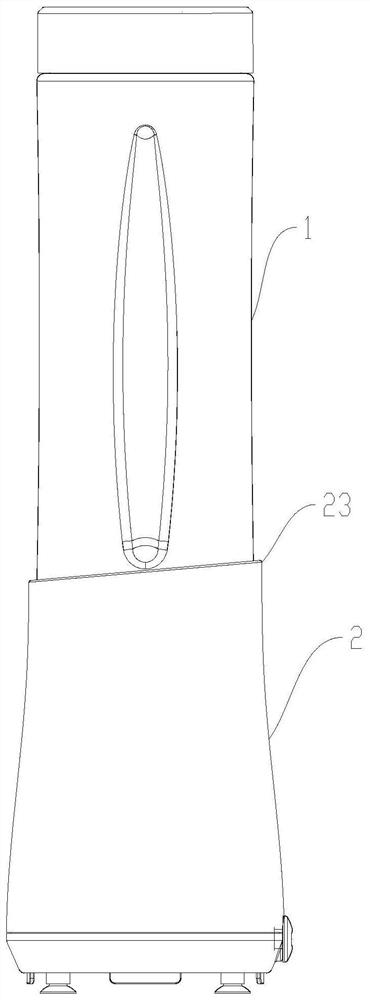
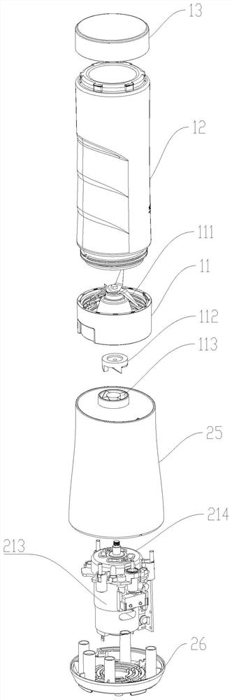
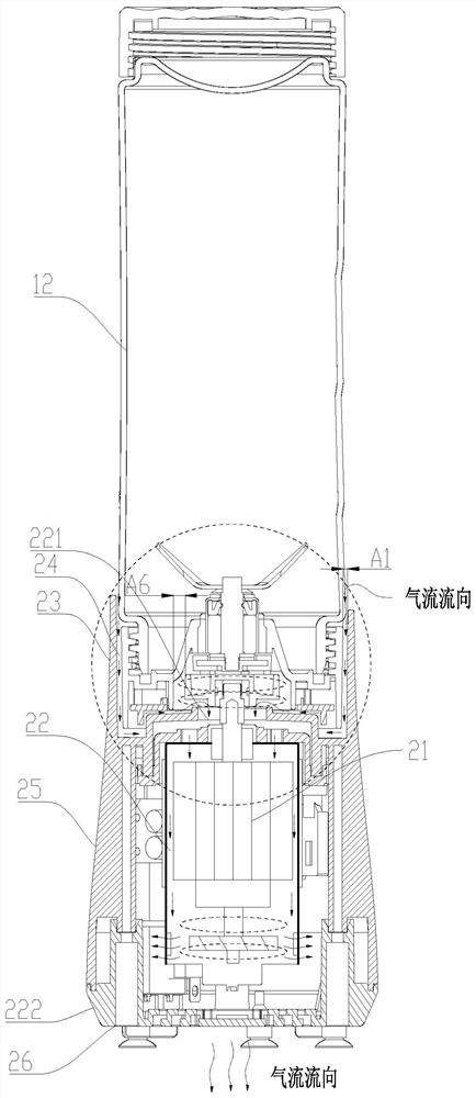
[0052] Such as Figure 1-Figure 4 As shown, a food processor with an optimized air duct structure disclosed in the present invention is an in-line food processor, including a main machine 2 and a processing cup assembly 1 installed on the main machine 2, and the processing cup assembly 1 can be connected with the The main machine 2 is detachably connected, and the processing cup assembly 1 and the main machine 2 can directly cooperate to realize the processing of food materials. The main engine 2 is provided with a motor assembly 21, the processing cup assembly 1 includes a knife seat assembly 11, a cup body 12 mounted on the knife seat assembly 11 and a cup cover 13 installed on the cup body, the knife seat assembly 11 includes a stirring member 111, The stirring member 111 is in transmission connection with the motor assembly 21 . In order to improve the heat dissipation efficiency of the motor assembly 21, a cooling air passage 22 is provided in the host machine 2. The coo...

Embodiment 2

[0066] Such as Figure 13-Figure 18 As shown, this embodiment is basically consistent with the technical solution disclosed in Embodiment 1, the only difference is that this embodiment is applied to other types of food processors (wall breaking machines, meat grinders, etc.), and the processing cup assembly 1 It is directly inserted into the main machine 2, and the air enters through the air gap between the outer wall of the tool holder assembly 11 and the inner wall of the main machine 2, and then passes through the negative pressure generated by the high-speed rotation of the fan 216 installed at the bottom of the upper connector 112, lower connector 113 and motor rotor 215, Make the external high-pressure airflow pass through the two negative pressure chambers set quickly through the set cooling air duct 22 and enter the interior of the host 2, and then follow the heat dissipation holes 261 of the base 26 to quickly discharge the heat in the host 2 to achieve The purpose of...


PUM


Abstract

The invention provides a food processor with an optimized air duct structure, which comprises a main machine and a processing cup assembly installed on the main machine, and a stirring piece driven by a motor assembly is arranged in the processing cup assembly; a cooling air duct is arranged in the main machine and comprises a first air inlet and a first air outlet, the first air inlet is close to the output end of the motor assembly, and the first air outlet is far away from the output end of the motor assembly. The cooling air duct is arranged in the main machine, the air inlet and the air outlet are formed in the two ends of the motor assembly respectively, external airflow can fully dissipate heat of the motor assembly after entering the main machine, and the distance between exhausted hot airflow and the air inlet is long, so that the situation that heat is accumulated due to the fact that the hot airflow is sucked into the main machine is avoided; the heat dissipation effect of the host is ensured and the service life of the whole machine is prolonged.

Description

technical field [0001] The invention relates to the field of food processing, in particular to a food processing machine with an optimized air duct structure. Background technique [0002] At present, the air duct structure of the food processing machine in the prior art is arranged at the bottom, with air inlet channels on both sides of the bottom, and an air outlet structure at the center of the bottom. The fan at the bottom of the motor rotates at high speed to form a certain negative pressure cavity in the air duct. The cold air from the outside flows along the motor to the negative pressure cavity, and the hot air in the cavity is brought out through the bottom air outlet structure. However, because the air inlet and outlet channels are too close, the temperature inside the main unit cannot be quickly discharged, and the heat convection will continue to circulate in the main unit, resulting in unsatisfactory cooling effect of the motor in the main unit and affecting the...

Claims


Application Information

Patent Timeline
IPC IPC(8): A47J43/046A47J43/07
CPCA47J43/046A47J43/0716
Inventor 王旭宁赵维松欧阳鹏斌
Owner HONGYANG HOME APPLIANCES
Why Eureka
Try Eureka