Oil seal pulling-out device

An external puller and oil seal technology, applied in the field of oil seal external puller, can solve the problems of large workload and low oil seal efficiency, and achieve the effects of improving applicability, improving work efficiency and shortening working time.

Inactive Publication Date: 2018-05-04
李林
View PDF0 Cites 0 Cited by
  • Summary
  • Abstract
  • Description
  • Claims
  • Application Information

AI Technical Summary

Problems solved by technology

Aiming at the low efficiency and heavy workload of manually pulling out the oil seal in the prior art, the present invention designs a tool that can simplify the manual operation so as to improve the pulling out efficiency; Cut out the unloading groove, and then place the U-shaped groove of the supporting base on the end face of the bearing. According to the distance between the unloading groove and the bottom of the U-shaped groove, move the pull-out rod in the hollow connecting block so that the pull-out rod The clamping disc at the end directly contacts the inner wall of the oil seal through the withdrawal groove, and then fixes the extraction rod in the connecting block through the threaded fit between the external thread and the inner wall of the connecting block, and then manually uses a wrench or other pneumatic equipment to start the alignment. The screw nut on the connecting block rotates, so that the connecting block moves upwards after being threaded with it in the through hole until the oil seal is completely pulled out; For different types of bearings, the position of the pull-out rod can be adjusted. Even if the distance between the side wall of the oil seal of each bearing and the bottom of the U-shaped groove is different, the pull-out rod can still accurately pass through the withdrawal groove and the bottom of the U-shaped groove. The inner wall of the oil seal is in contact, which greatly improves the applicability of the present invention

Method used


Image

  • Oil seal pulling-out device
  • Oil seal pulling-out device

Examples


Embodiment 1

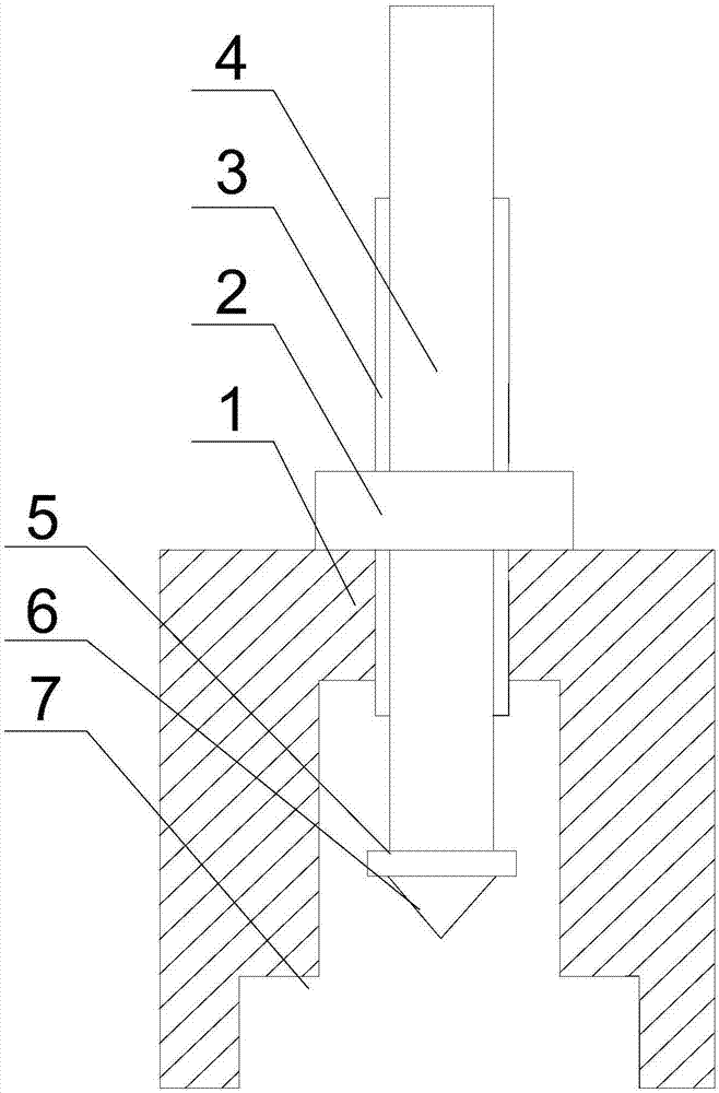
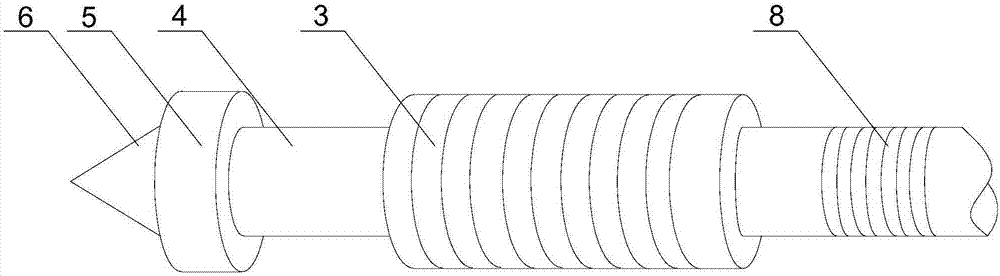
[0020] Such as figure 1 and figure 2 As shown, this embodiment includes a support base 1 with a U-shaped groove at the bottom, a through hole is opened at the upper end of the support base 1, and the pull-out rod 4 is placed in the U-shaped groove through the through hole, and the pull-out rod 4 The middle part of the sleeve is provided with a hollow and annular connection block 3, the connection block 3 is threadedly matched with the through hole, and an external thread 8 is also provided on the outer wall of the extraction rod 4, and the external thread 8 is connected with the connection block 3 is threaded on the upper part of the inner wall, and the end of the extraction rod 4 is equipped with a snap-in disc 5, and the outer diameter of the snap-in disc 5 is greater than the outer diameter of the extraction rod 4; it also includes a screw nut 2, and the screw nut 2 is connected to the The connecting block 3 is threaded.

[0021] When working, manually cut out the tempor...


PUM


Abstract

The invention discloses an oil seal pulling-out device. The oil seal pulling-out device comprises a supporting base with a U-shaped groove formed in the bottom, and a through hole is formed in the upper end of the supporting base. A pulling-out rod penetrates the through hole to be arranged in the U-shaped groove, and the middle of the pulling-out rod is sleeved with a hollow annular connecting block. The connecting block is in threaded fit with the through hole, and an external thread is arranged on the outer wall of the pulling-out rod. The external thread is in threaded fit with the upper section of the inner wall of the connecting block. A clamp-connecting disc is mounted at the tail end of the pulling-out rod, and the outer diameter of the clamp-connecting disc is larger than that ofthe pulling-out rod. A nut is further included and is in threaded fit with the connecting block. The oil seal pulling-out device is small and exquisite in overall structure, detachable connection between all the components can be achieved, and manual use is convenient; the position of the pulling-out rod can be adjusted according to various bearings of different types, even though the distances between the side walls of oil seals of the bearings and the groove bottom of the U-shaped groove are different, the pulling-out rod can still accurately penetrate a withdrawing groove to be in contact with the inner walls of the oil seals, and therefore the applicability of the oil seal pulling-out device is improved.

Description

technical field [0001] The invention relates to an LL type oil seal, in particular to an oil seal external puller. Background technique [0002] The LL type oil seal is used for the sealing of the 353130B compact bearing, which can achieve the purpose of making the short shaft of the 353130B compact bearing less prone to bending and increasing the service life. Abrasive particles invade the bearing, which also makes the bearing have good sealing performance and improves the service life of the grease in the bearing. [0003] However, during the long-term operation of the locomotive, in order to ensure the stable operation of the locomotive, it is necessary to detect and replace the LL-type oil seal in time and regularly. During the replacement process of the LL-type oil seal, the temporarily sealed oil seal unloading groove is usually opened. Then use tools such as pliers to pull the oil seal out of the bearing. Since the press-fitting of the LL-type oil seal is realized th...

Claims


Application Information

Patent Timeline
Patent Type & Authority Applications(China)
IPC IPC(8): B25B27/02
CPCB25B27/02
Inventor 李林
Owner 李林
Why Eureka
Try Eureka