Combined type end beam connecting structure

A connection structure and combined technology, applied in the direction of support structure, bottom support structure, lifting equipment braking device, etc., can solve the problem that the door legs cannot be freely converted into rigid and flexible leg structures, etc., to achieve convenient conversion and reduce horizontal deformation , the effect of free conversion

Active Publication Date: 2018-05-08
SINOHYDRO JIAJIANG HYDRAULIC MACHINERY +1
View PDF8 Cites 0 Cited by
  • Summary
  • Abstract
  • Description
  • Claims
  • Application Information

AI Technical Summary

Problems solved by technology

[0005] In order to overcome the defects and deficiencies in the above-mentioned prior art, the present application provides a combined end beam connection structure. The present application aims to solve the problem that the door leg fixing in the prior art cannot realize the free conversion of the rigid-flexible leg structure

Method used


Image

  • Combined type end beam connecting structure
  • Combined type end beam connecting structure
  • Combined type end beam connecting structure

Examples


Embodiment 1

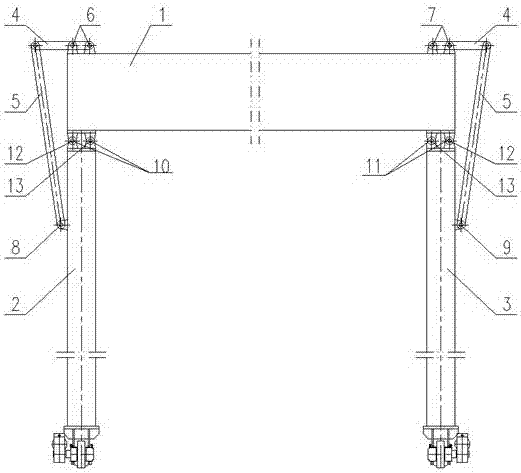
[0019] As a preferred embodiment of the application, refer to the attached figure 1 , this example discloses:

[0020] A combined end-beam connection structure, including a main beam 1, and the lower sides of the left and right ends of the main beam 1 are respectively provided with outriggers A2 and outriggers B3, and is characterized in that it also includes a horizontal support 4 and an oblique support 5 , the top surfaces of the left and right ends of the main beam 1 are respectively fixed with a fixed hinge assembly A6 and a fixed hinge assembly B7; the outer surface of the leg A2 is fixed with a fixed hinge E8, and the leg B3 A fixed hinge F9 is fixedly arranged on the outer surface; the fixed hinge E8 and the fixed hinge F9 are respectively used to hinge with the lower end of the diagonal support 5, and the upper end of the diagonal support 5 is hinged with one end of the horizontal support 4 The other end of the horizontal support 4 is connected with the fixed hinge as...

Embodiment 2

[0023] As another preferred embodiment of the present application, refer to the attached figure 1 , this example discloses:

[0024] A combined end-beam connection structure, including a main beam 1, and the lower sides of the left and right ends of the main beam 1 are respectively provided with outriggers A2 and outriggers B3, and is characterized in that it also includes a horizontal support 4 and an oblique support 5 , the top surfaces of the left and right ends of the main beam 1 are respectively fixed with a fixed hinge assembly A6 and a fixed hinge assembly B7; the outer surface of the leg A2 is fixed with a fixed hinge E8, and the leg B3 A fixed hinge F9 is fixedly arranged on the outer surface; the fixed hinge E8 and the fixed hinge F9 are respectively used to hinge with the lower end of the diagonal support 5, and the upper end of the diagonal support 5 is hinged with one end of the horizontal support 4 The other end of the horizontal support 4 is connected with the ...

Embodiment 3

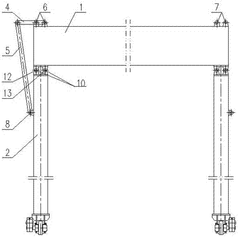
[0026] As another preferred embodiment of the present application, refer to the attached figure 2 , this example discloses:

[0027]A combined end-beam connection structure, including a main beam 1, and the lower sides of the left and right ends of the main beam 1 are respectively provided with outriggers A2 and outriggers B3, and is characterized in that it also includes a horizontal support 4 and an oblique support 5 , the top surfaces of the left and right ends of the main beam 1 are respectively fixed with a fixed hinge assembly A6 and a fixed hinge assembly B7; the outer surface of the leg A2 is fixed with a fixed hinge E8, and the leg B3 A fixed hinge F9 is fixedly arranged on the outer surface; the fixed hinge E8 and the fixed hinge F9 are respectively used to hinge with the lower end of the diagonal support 5, and the upper end of the diagonal support 5 is hinged with one end of the horizontal support 4 The other end of the horizontal support 4 is connected with the ...


PUM


Abstract

The invention discloses a combined type end beam connecting structure and relates to the technical field of cranes. The combined type end beam connecting structure comprises a main beam, a supportingleg A, a supporting leg B, a horizontal supporting part and an inclined supporting part. A fixed trunnion assembly A and a fixed trunnion assembly B are arranged on the top faces of the left end and the right end of the main beam separately. A fixed trunnion E is fixedly arranged on the outer side face of the supporting leg A, and a fixed trunnion F is fixedly arranged on the outer side face of the supporting leg B. The upper end of the supporting leg A is connected with the main beam through a trunnion assembly C, and the upper end of the supporting leg B is connected with the main beam through a trunnion assembly D. The combined type end beam connecting structure can meet different working condition requirements since a rigid-flexible leg structure can be freely combined.

Description

technical field [0001] The invention relates to the technical field of cranes, in particular to a combined end beam connection structure of a gantry crane. Background technique [0002] With the continuous and rapid development of my country's economy, the demand for cranes is also increasing. As large-scale special equipment in the infrastructure and logistics and transportation industries, gantry cranes have become essential key equipment for many construction sites; The outriggers of traditional gantry cranes use box-shaped pillar components. This structure is safe and stable, but it is inconvenient to install and maintain. With the development of technology, current cranes generally use a rigid outrigger and a flexible outrigger to improve the stability of the crane. sex. Existing gantry lifting equipment is generally in the form of a fixed door leg structure, such as rigid leg-rigid leg, rigid leg-semi-flexible leg, rigid leg-flexible leg and other combinations. [0003...

Claims


Application Information

Patent Timeline
Patent Type & Authority Applications(China)
IPC IPC(8): B66C5/02B66C6/00
CPCB66C5/02B66C6/00
Inventor 黄文峰陈杰杨康王兵姚启文裘伟李钰康
Owner SINOHYDRO JIAJIANG HYDRAULIC MACHINERY
Why Eureka
Try Eureka