A combined end beam connection structure
A connection structure and combined technology, applied in the direction of support structure, bottom support structure, hoisting device, etc., can solve the problem that the door legs cannot be freely converted into rigid-flexible leg structures, etc., to achieve convenient conversion, reduce horizontal deformation, and free The effect of conversion
- Summary
- Abstract
- Description
- Claims
- Application Information
AI Technical Summary
Problems solved by technology
Method used
Image
Examples
Embodiment 1
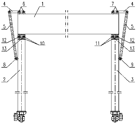
[0019] As a preferred embodiment of the application, refer to the attached figure 1 , this example discloses:
[0020] A combined end-beam connection structure, including a main beam 1, and the lower sides of the left and right ends of the main beam 1 are respectively provided with outriggers A2 and outriggers B3, and is characterized in that it also includes a horizontal support 4 and an oblique support 5 , the top surfaces of the left and right ends of the main beam 1 are respectively fixed with a fixed hinge assembly A6 and a fixed hinge assembly B7; the outer surface of the leg A2 is fixed with a fixed hinge E8, and the leg B3 A fixed hinge F9 is fixedly arranged on the outer surface; the fixed hinge E8 and the fixed hinge F9 are respectively used to hinge with the lower end of the diagonal support 5, and the upper end of the diagonal support 5 is hinged with one end of the horizontal support 4 The other end of the horizontal support 4 is connected with the fixed hinge as...
Embodiment 2
[0023] As another preferred embodiment of the present application, refer to the attached figure 1 , this example discloses:
[0024] A combined end-beam connection structure, including a main beam 1, and the lower sides of the left and right ends of the main beam 1 are respectively provided with outriggers A2 and outriggers B3, and is characterized in that it also includes a horizontal support 4 and an oblique support 5 , the top surfaces of the left and right ends of the main beam 1 are respectively fixed with a fixed hinge assembly A6 and a fixed hinge assembly B7; the outer surface of the leg A2 is fixed with a fixed hinge E8, and the leg B3 A fixed hinge F9 is fixedly arranged on the outer surface; the fixed hinge E8 and the fixed hinge F9 are respectively used to hinge with the lower end of the diagonal support 5, and the upper end of the diagonal support 5 is hinged with one end of the horizontal support 4 The other end of the horizontal support 4 is connected with the ...
Embodiment 3
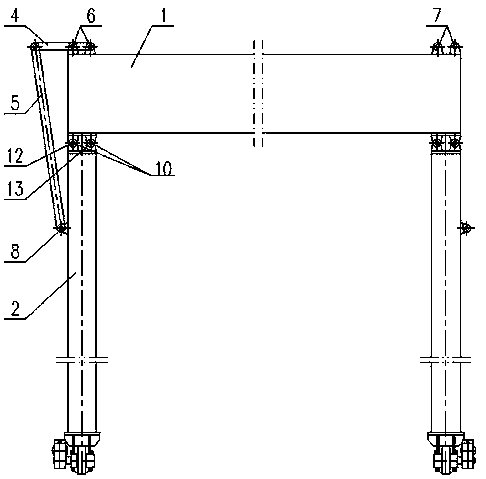
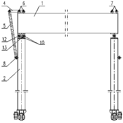
[0026] As another preferred embodiment of the present application, refer to the attached figure 2 , this example discloses:
[0027]A combined end-beam connection structure, including a main beam 1, and the lower sides of the left and right ends of the main beam 1 are respectively provided with outriggers A2 and outriggers B3, and is characterized in that it also includes a horizontal support 4 and an oblique support 5 , the top surfaces of the left and right ends of the main beam 1 are respectively fixed with a fixed hinge assembly A6 and a fixed hinge assembly B7; the outer surface of the leg A2 is fixed with a fixed hinge E8, and the leg B3 A fixed hinge F9 is fixedly arranged on the outer surface; the fixed hinge E8 and the fixed hinge F9 are respectively used to hinge with the lower end of the diagonal support 5, and the upper end of the diagonal support 5 is hinged with one end of the horizontal support 4 The other end of the horizontal support 4 is connected with the ...
PUM
 Abstract
Description
Claims
Application Information
 - R&D
- Intellectual Property
- Life Sciences
- Materials
- Tech Scout
- Unparalleled Data Quality
- Higher Quality Content
- 60% Fewer Hallucinations
Browse by: Latest US Patents, China's latest patents, Technical Efficacy Thesaurus, Application Domain, Technology Topic, Popular Technical Reports.
© 2025 PatSnap. All rights reserved.Legal|Privacy policy|Modern Slavery Act Transparency Statement|Sitemap|About US| Contact US: help@patsnap.com


