
A Calculation Method of Structural Stress Sensitivity

A technology of structural stress and sensitivity, applied in special data processing applications, instruments, geometric CAD, etc., can solve the problem of difficulty in the process of solving stress sensitivity, and achieve the effect of improving the solution efficiency.

Active Publication Date: 2021-08-17
CHINA AIRPLANT STRENGTH RES INST
View PDF6 Cites 0 Cited by
  • Summary
  • Abstract
  • Description
  • Claims
  • Application Information

AI Technical Summary

Problems solved by technology

[0003] With the development of technologies such as the integration of materials and structures, the scale of variables that can be designed in the structure is increasing. The fine optimization design based on the optimization model with more than 100,000 variables has been put on the agenda. In order to carry out the fine design of the structure, the stress must be considered as Due to the development of process preparation technology, the design results of stress control by unit can be directly manufactured without going through the traditional rounding process. From the perspective of program flow organization, the use of stiffness matrix inversion is sensitive to large variables. Degree calculation is the most efficient program implementation method. Since the stiffness matrix is ​​usually singular, the conventional matrix inversion algorithm will encounter numerical solution difficulties, making it difficult to solve the stress sensitivity.

Method used


Image

  • A Calculation Method of Structural Stress Sensitivity
  • A Calculation Method of Structural Stress Sensitivity
  • A Calculation Method of Structural Stress Sensitivity

Examples


Embodiment Construction

[0019] In order to make the objectives, technical solutions and advantages of the present invention clearer, the technical solutions in the embodiments of the present invention will be described in more detail below in conjunction with the drawings in the embodiments of the present invention. In the drawings, the same or similar reference numerals denote the same or similar elements or elements having the same or similar functions throughout. The described embodiments are some, but not all, embodiments of the invention. The embodiments described below by referring to the figures are exemplary and are intended to explain the present invention and should not be construed as limiting the present invention. Based on the embodiments of the present invention, all other embodiments obtained by persons of ordinary skill in the art without creative efforts fall within the protection scope of the present invention. Embodiments of the present invention will be described in detail below ...


PUM


Abstract

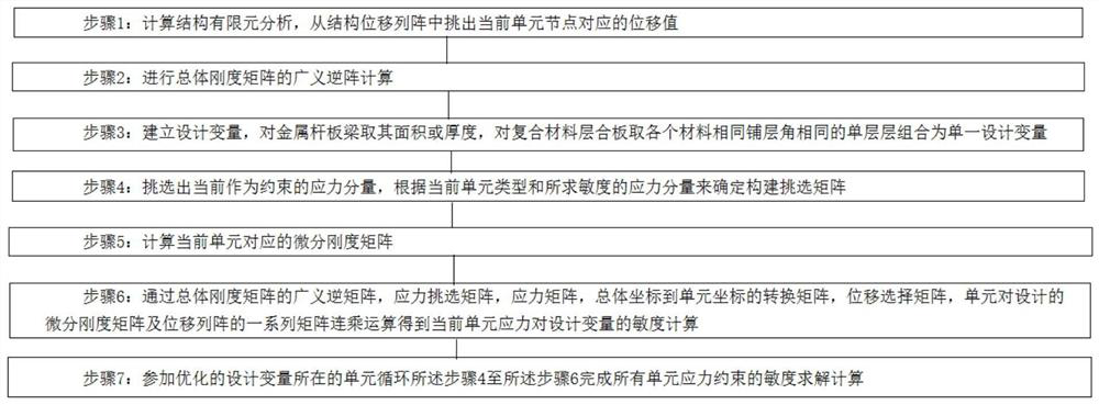
The invention discloses a method for solving structural stress sensitivity. The method for solving the structural stress sensitivity includes the following steps: Step 1: calculate the structural finite element analysis, and pick out the displacement value corresponding to the current unit node from the structural displacement array; Step 2: perform the generalized inverse calculation of the overall stiffness matrix; Step 3: Establish design variables, take the area or thickness of the metal bar-slab girder, and take the single-layer combination of the same material and the same ply angle as the single design variable for the composite laminated plate; Step 4: Select the current stress as the constraint Component, according to the current element type and the stress component of the sensitivity to be determined to construct the selection matrix; Step 5: Calculate the differential stiffness matrix corresponding to the current element; Step 6: Through the generalized inverse matrix, the stress selection matrix, the stress matrix, and the overall coordinates to The conversion matrix of unit coordinates, displacement selection matrix, a series of matrix multiplication operations of the designed differential stiffness matrix and displacement array to obtain the sensitivity calculation of the current unit stress to the design variables; Step 7: loop through the above steps 4 to The step 6 completes the sensitivity solution calculation of all element stress constraints.

Description

technical field [0001] The invention relates to the technical field of structural stress analysis, in particular to a method for solving structural stress sensitivity. Background technique [0002] Optimization technology is the only way to meet the increasing requirements of aircraft comprehensive performance and from inherited design, experience design to innovative design. [0003] With the development of technologies such as the integration of materials and structures, the scale of variables that can be designed in the structure is increasing. The fine optimization design based on the optimization model with more than 100,000 variables has been put on the agenda. In order to carry out the fine design of the structure, the stress must be considered as Due to the development of process preparation technology, the design results of stress control by unit can be directly manufactured without going through the traditional rounding process. From the perspective of program flow...

Claims


Application Information

Patent Timeline
Patent Type & Authority Patents(China)
IPC IPC(8): G06F30/23G06F30/17G06F119/14G06F111/04G06F113/26
CPCG06F30/17G06F30/23
Inventor 王立凯罗利龙聂小华郭瑜超艾森
Owner CHINA AIRPLANT STRENGTH RES INST
Learn More