
A power cable connector

A technology for connecting joints and power cables, which is applied in the connection, the parts of the connecting device, the connection where permanent deformation works, etc., can solve the problems of safety threats to ground operators, weak grip of the wrench, poor use effect, etc. To achieve the effect of simple structure, good use effect and high safety

Active Publication Date: 2019-07-30
广东庆丰电缆集团有限公司
View PDF5 Cites 2 Cited by
  • Summary
  • Abstract
  • Description
  • Claims
  • Application Information

AI Technical Summary

Problems solved by technology

[0002] At present, in electric power construction operations, when connecting and continuing the cable ends, wire lugs are usually used as connection devices. The wire lug is fixedly connected by bolts. The cable connection operation is usually carried out at high altitude. When tightening the bolts, two wrenches are required, one is used to fix the bolts and the other is used to tighten the nuts. The fastening of bolts has certain dangers for hands detached from the support surface for high-altitude operations. In order to ensure the fastness of the connection, the bolts are usually tightened very tightly, which requires a certain strength for the muscles of the arms of the workers. Long-term work will make the The operator's arm is sore, and the wrench is not firmly held and may fall, which poses a threat to the safety of the ground operator, and the use effect is not good

Method used


Image

  • A power cable connector

Examples


Embodiment Construction

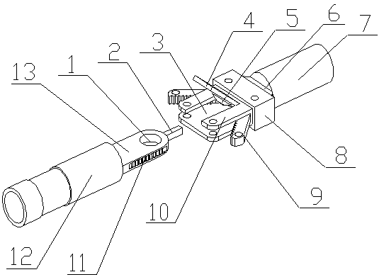
[0023] A power cable connection joint of the present invention is realized in this way. When in use, when carrying out electric power construction, firstly peel the connection end of one of the cables and put it into the main connection sleeve (7), and peel the connection end of the other cable Then put it into the auxiliary connecting sleeve (12), and then use the crimping nose pliers to press and fix it separately, and then extend the connecting piece (13) between the limit plate (10) and the support plate (3), and the connecting piece ( 13) Drive the limit rod (2) to move into the strip groove on the connecting plate (6), and then rotate the two clamping plates (9), so that the two clamping plates (9) are respectively clamped on the connecting plate (13) On both sides of the two clamping plates (9), the locking teeth (11) on the two clamping plates (9) are locked and fixed with the locking teeth (11) on both sides of the connecting piece (13), and then the two sides of the c...


PUM


Abstract

The invention discloses a connector device which can connect slave-master connecting devices through a single-hand suspended operation so as to connect a cable when high-altitude work is performed. The power cable connecting joint is characterized in that one side of a connecting plate is arranged at one end of a main connecting sleeve, the inner wall of the main connecting sleeve is provided witha plurality of conical bulges, the main connecting sleeve is made of copper, the internal part of the connecting plate is provided with a strip-shaped slot, one side of a supporting plate is arrangedat the other side of the connecting plate, the supporting plate is provided with two through holes which are close to the other side of the supporting plate, one side of a limiting plate is arrangedat the other side of the connecting plate, the limiting plate is located above the supporting plate, the limiting plate is provided with two through holes which respectively correspond to the two through holes in the supporting plate, the limiting plate is provided with a square groove, a pressing plate is arranged in the square groove and is hinged with the limiting plate, a limiting bulge is arranged on the pressing plate and faces towards the supporting plate, the limiting bulge is hemispherical, and two clamping plates are located between the limiting plate and the supporting plate and arerespectively located at two sides of the pressing plate.

Description

technical field [0001] The invention relates to a power cable connection joint, which relates to a connection head device for connecting power cables used in power construction, and belongs to the field of power construction. In particular, it relates to a connector device capable of connecting two parent-child connectors and then connecting cables by one-handed suspension operation during high-altitude operations. Background technique [0002] At present, in electric power construction operations, when connecting and continuing the cable ends, wire lugs are usually used as connection devices. The wire lug is fixedly connected by bolts. The cable connection operation is usually carried out at high altitude. When tightening the bolts, two wrenches are required, one is used to fix the bolts, and the other is used to tighten the nuts. The fastening of bolts has a certain danger for the two hands of the high-altitude operation to be separated from the support surface, and in or...

Claims


Application Information

Patent Timeline
Patent Type & Authority Patents(China)
IPC IPC(8): H01R13/629H01R4/18H01R13/639
CPCH01R4/18H01R13/629H01R13/639
Inventor 不公告发明人
Owner 广东庆丰电缆集团有限公司
Learn More