Multifunctional electric wheelchair

An electric wheelchair and multi-functional technology, which can be used in patient chairs or special transportation tools, vehicle rescue, medical transportation, etc., and can solve problems such as inconvenience to carry, entanglement of electrical connection lines, and reduced maintenance efficiency.

Pending Publication Date: 2018-05-11
NANJING KANGNI MECHANICAL & ELECTRICAL
View PDF16 Cites 7 Cited by
  • Summary
  • Abstract
  • Description
  • Claims
  • Application Information

AI Technical Summary

Problems solved by technology

Although the seat on these wheelchairs can rotate relative to the vehicle body (chassis part), the seat and the vehicle body part cannot be easily separated unless they are disassembled.
And if the rotation of the seat needs to be driven by the driving mechanism, it will be more restricted by the driving mechanism, and it will be more difficult to mechanically separate the seat from the car body.
However, even if the seat and the car body can be easily separated, if the control wire is arranged on the seat, it will be hindered by the electric connecting wire. For example, the patent application of the Taiwan region whose publication number is TW466948U has a control wire on the seat. , it is difficult to completely separate the seat from the body for this type of wheelchair
However, the functions of the integrated wheelchair in which the seat and the body cannot be separated are fixed, which is inconvenient for the user to increase the functions of the wheelchair, and it is also inconvenient to carry. For example, the existing electric wheelchair cannot be loaded i

Method used


Image

  • Multifunctional electric wheelchair
  • Multifunctional electric wheelchair
  • Multifunctional electric wheelchair

Examples


Embodiment l

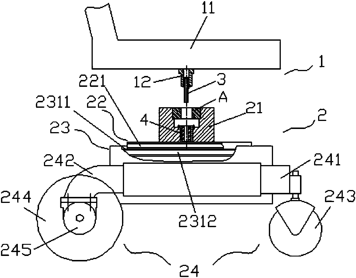
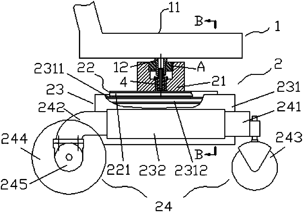
[0093] Such as figure 1 , 2 , The electric wheelchair includes a multi-core plug 3 and a multi-core socket 4 through which a seat platform 1 and a chassis platform 2 are plugged together. The seat platform 1 includes a seat 11 and a rotating shaft 12 fixed at the bottom of the seat; the chassis platform 2 includes a chassis, a base 21 and a connecting bracket 22; and the chassis includes a chassis box 23 and a walking bracket 24 arranged on the chassis box . The connecting bracket 22 is arranged above the chassis, the base 21 is connected to the connecting bracket 22, and a socket A is arranged on it; the multi-core plug 3 is connected to the lower end of the rotating shaft and is concentric with the rotating shaft, and the multi-core socket 4 is connected below the socket On the base 21 and concentric with the center of the receptacle. The seat 11 is inserted into or pulled out of the socket A through the rotating shaft 12. At the same time, the multi-core plug 3 at the lo...

Embodiment 2

[0103] Such as Figure 8 , the electric wheelchair of the present embodiment is basically the same as the above-mentioned embodiment 1, that is, the electric wheelchair includes a seat platform 1, a chassis platform 2, a multi-core plug 3 and a multi-core socket 4; the same chassis platform 2 includes a chassis, a base 21 And the connection bracket 22; but the seat platform 1 also includes a rotating body 13 in addition to the seat 11 and the rotating shaft 12 fixed on the bottom of the seat. The rotating body 13 of this embodiment is a rotating body in a tapered roller bearing, which is supported by the bearing inner ring (not shown) in the tapered roller bearing, the cage (not shown) connected to the bearing inner ring and the It is composed of tapered rollers (not shown) on the cage, and the rotating body is connected to the rotating shaft through the inner ring of the bearing; the outer ring of the bearing replaces the socket A in Embodiment 1, and serves as the supporting...

Embodiment 3

[0107] Such as Figure 9 , 10 11. The electric wheelchair of this embodiment adds a lifting module 25 on the basis of Embodiment 2, so that the seat platform has the function of lifting up and down on the basis of being detachable relative to the chassis platform and having a horizontal rotation function.

[0108] The lifting module 25 includes a scissor lifting bracket mainly composed of a front scissor foot 2511 and a rear scissor foot 251 and a lifting motor 250 with an axially movable output shaft 2501 . The scissor lifting bracket adopts a known scissor lifting device, such as the Chinese patent application whose publication number is CN 105731296 A. The lifting motor with an axially movable output shaft adopts the structure disclosed by a motor whose notification number is CN 205212628 U, wherein the screw rod 4 is used as the axially movable output shaft of the lifting motor in the lifting module.

[0109] The lifting bracket is mainly composed of scissor feet. The li...


PUM


Abstract

The invention relates to a multifunctional electric wheelchair. The wheelchair comprises a seat platform, a chassis platform, a base, connecting supporting rods, a multi-pin connector and a multi-pinsocket, wherein the multi-pin connector and the multi-pin socket are connected with one another in an inserted mode; the seat platform comprises a seat and a rotary shaft fixed at the bottom of the seat; the chassis platform comprises a chassis box body and walking supporting rods arranged on the chassis box body; the base is arranged on the connecting supporting rods and at least provided with asocket; the multi-pin connector or the multi-pin socket is coaxially connected with the rotary shaft at the lower end of the rotary shaft, and the corresponding multi-pin connector or the multi-pin socket is coaxially connected with the socket on the base below the socket; the connection or separation between the seat and the chassis platform is achieved by inserting the rotary shaft in the socketor pulling the rotary shaft out from the socket and by inserting the multi-pin connector at the lower end of the rotary shaft in the multi-pin socket on the base or pulling the multi-pin connector onthe base out from the multi-pin socket at the lower end of the rotary shaft. The combination and separation between the seat and the chassis on the wheelchair can be achieved through the inserted mode, and a wheelchair with required functions can be built and formed by selecting corresponding functional modules according to demands of the functions.

Description

technical field [0001] The invention relates to a multifunctional electric wheelchair. Background technique [0002] The various electric wheelchairs that have been disclosed may have other functions in addition to being used as a means of transportation, such as rotating functions, lifting functions and swing functions (including self-balancing follow-up functions). patent application. Although the seat on these wheelchairs can rotate relative to the vehicle body (chassis part), the seat and the vehicle body part can not be easily separated unless dismounted. And if the rotation of the seat needs to be driven by the driving mechanism, it will be more restricted by the driving mechanism, and it is more difficult to mechanically separate the seat and the car body part easily. However, even if the seat and the car body can be easily separated, if the control wire is arranged on the seat, it will be hindered by the electric connecting wire. For example, the patent application...

Claims


Application Information

Patent Timeline
IPC IPC(8): A61G5/04A61G5/10
CPCA61G5/04A61G5/10A61G5/1056A61G2220/14A61G2203/70
Inventor 金元贵柯旭尹琨费凯成李宏史翔贡智兵
Owner NANJING KANGNI MECHANICAL & ELECTRICAL
Why Eureka
Try Eureka