Crack deformation monitor

A monitor and deformation technology, applied in the field of measurement, can solve problems such as the measurement function of bending deformation without cracks, and achieve the effect of comprehensive and accurate monitoring and response

Active Publication Date: 2018-05-11
HUNAN CITY UNIV
View PDF17 Cites 3 Cited by
  • Summary
  • Abstract
  • Description
  • Claims
  • Application Information

AI Technical Summary

Problems solved by technology

[0002] At present, the fracture monitor can measure the fracture width, the translation and dislocation of both sides of the fracture, etc., but it has no function of crack bending deformation measurement

Method used


Image

  • Crack deformation monitor
  • Crack deformation monitor
  • Crack deformation monitor

Examples


Embodiment 1

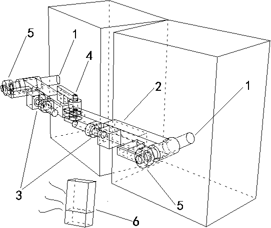
[0020] Such as Figure 1-3 As shown, the crack deformation monitor includes two columns, a measuring rod, a telescopic displacement sensor A, an angle sensor A, an angle sensor B and a data monitoring terminal. The two columns are fixedly installed on the structures on both sides of the crack, and the two columns are perpendicular to their respective structures. Plane, the two ends of the measuring rod are cylinders, the direction of the generatrix of the cylinder is at a certain angle to the measuring rod, the inner diameter of the cylinder is equal to the outer diameter of the column, the two cylinders are set outside the two columns, and one or both sides of the measuring rod have a telescopic structure, and A telescopic displacement sensor A is installed at the telescopic structure, and there is a uniaxial rotation structure in the middle of the measuring rod, and an angle sensor A is installed at the uniaxial rotation structure, and an angle sensor B is installed at the co...

Embodiment 2

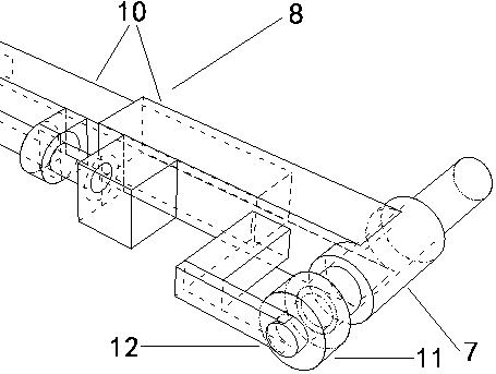
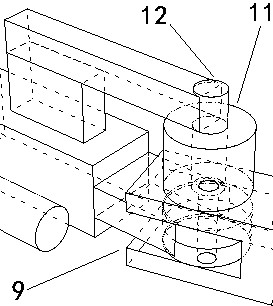
[0026] Such as Figure 4 As shown, on the basis of Embodiment 1, a telescopic displacement sensor B is also included, which is installed on a certain column. The cylinder on the column and the angle sensor B have a space for sliding up and down. The cylinder and the column are fixedly connected, and the cylinder and the angle sensor B on the other column are restricted from sliding up and down. The telescopic displacement sensor B can measure the dislocation of cracks with high precision, and is suitable for the situation where the dislocation of cracks is obvious; if the telescopic displacement sensor B is not installed in Example 1, the dislocation can also be calculated by the deformation of the measuring rod, and is suitable for the situation where the dislocation of cracks is small. The telescopic displacement sensor may be a magnetostrictive displacement gauge.


PUM


Abstract

The problem to be solved by the invention is how to make a crack monitor have a bending deformation monitoring function. The crack deformation monitor includes two vertical columns, a measuring rod, atelescopic displacement sensor(s) A, an angle sensor A, an angle sensor(s) B, and a data monitoring end. The two vertical columns are fixedly installed on structures on both sides of a crack. The twovertical columns are perpendicular to planes of the respective structures. Both ends of the measuring rod are cylinders. Generatrix directions of the cylinders are at an angle with the measuring rod.The inside diameter of the cylinders is equal to the outside diameter of the vertical columns. The two vertical columns are sleeved with the two cylinders. The measuring rod has a telescopic structure on one side or both sides and the telescopic displacement sensor A is installed at each telescopic structure. A single axis rotation structure is at the middle of the measuring rod, and the angle sensor A is installed at the single axis rotation structure. The angle sensor B is installed at the vertical column and cylinder on one side or the angle sensors B are installed at the vertical columnsand cylinders on both sides. Data measured by all the sensors are transmitted to the data monitoring end by a wireless or wired manner. The monitoring functions are organically integrated through themeasuring rod, and the crack deformation monitor is comprehensive and accurate.

Description

technical field [0001] The invention relates to the field of measurement technology, especially the monitoring of structures, buildings or ground cracks. Background technique [0002] At present, the fracture monitor can measure data such as fracture width, translation and dislocation on both sides of the fracture, but it has not been seen to have the function of measuring fracture bending deformation. [0003] The so-called bending deformation means that the two sides of the crack rotate along the axis of the crack, so that the planes where the two sides are located are no longer parallel. When the crack is squeezed face-to-face, it is easy to bend and deform. For example, when the bridge is impacted by a huge water flow, bending may occur at the impact. This deformation poses a great threat to the structural stability on both sides of the crack. [0004] Bending deformation does not appear in the relative translation of the two sides of the crack on the plane, nor does i...

Claims


Application Information

Patent Timeline
Patent Type & Authority Applications(China)
IPC IPC(8): G01B21/32G01B21/02
CPCG01B21/02G01B21/32
Inventor 张习科熊立伟李羲
Owner HUNAN CITY UNIV
Why Eureka
Try Eureka