Injection valve and adhesive dispensing system with same

A jet valve and valve body technology, applied in the field of dispensing valves, can solve the problems of inability to fine-tune glue fluid before spraying, troublesome use of supporting equipment, etc.

Inactive Publication Date: 2018-05-15
江苏冠达通电子科技有限公司
View PDF8 Cites 3 Cited by
  • Summary
  • Abstract
  • Description
  • Claims
  • Application Information

AI Technical Summary

Problems solved by technology

[0003] The existing injection valve and dispensing system are troublesome to use in conjunction with each other. It is necessary to schedule seasoning matters, and it is impossible to fine-tune the pre-spraying of the glue fluid.

Method used


Image

  • Injection valve and adhesive dispensing system with same

Examples


Embodiment

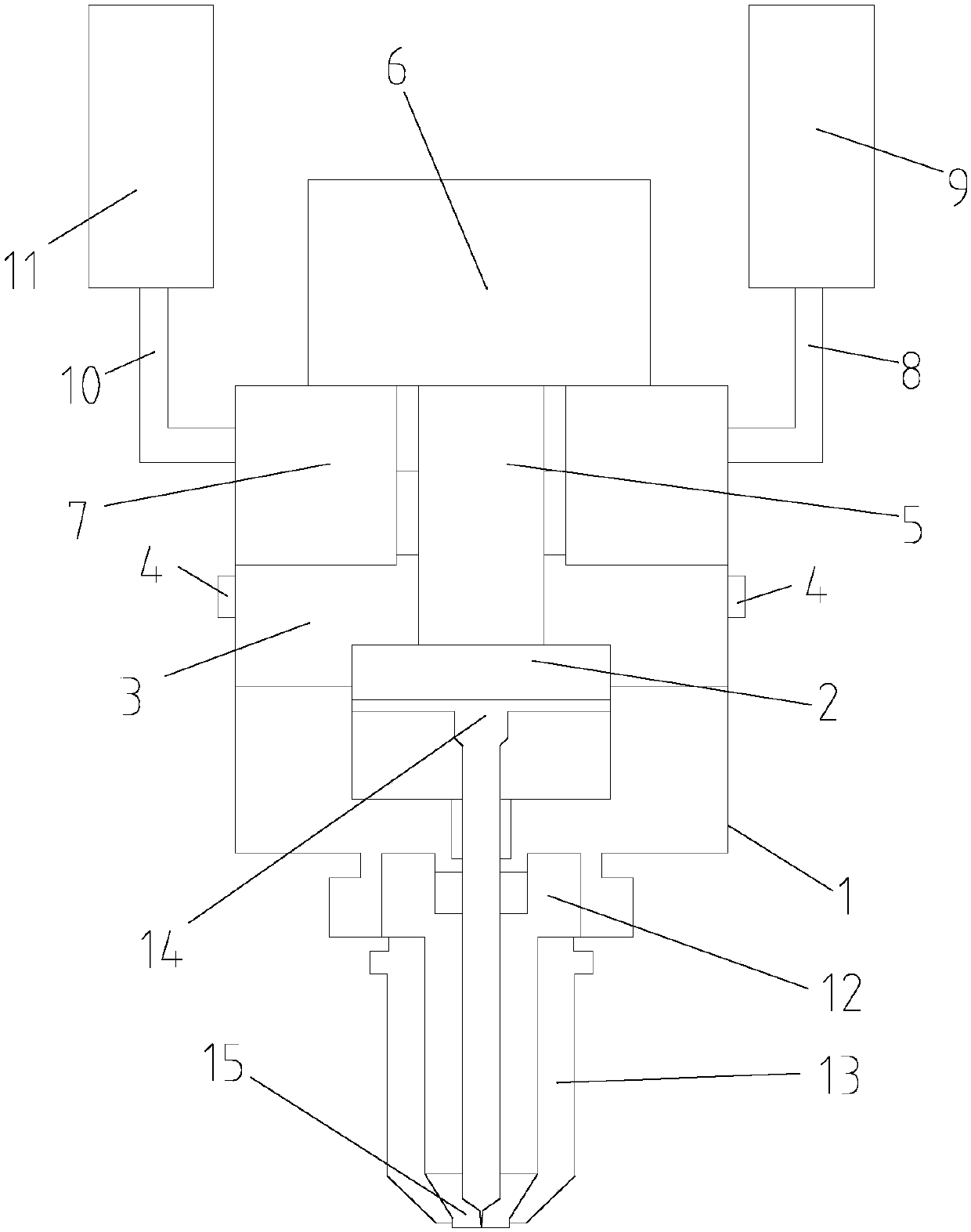
[0016] See attached figure 1 As shown, a jet valve in this embodiment includes a valve body 1, a cavity for accommodating glue is formed in the valve body 1, and a cavity corresponding to the cavity is opened on the side wall of the valve body 1. The valve body 1 is formed with a glue outlet 15 communicating with the cavity, and the cavity is divided up and down with a first chamber 7, a second chamber 3 and a third chamber 14 , the third chamber 14 communicates with the glue nozzle 15; the third chamber 14 is provided with a piston 2, and the edge of the piston 2 is attached to the inner wall of the third chamber 14; The top of the piston 2 is connected with one end of the adjustment rod 5, and the other end of the adjustment rod 5 penetrates upwards through the second chamber 3, and the first chamber 7 is connected with the drive cylinder 6 outside the valve body 1; A first flow channel is provided between the chamber 3 and the third chamber 14, and a blocking portion capab...


PUM


Abstract

The invention discloses an injection valve and an adhesive dispensing system with the injection valve. The injection valve comprises a valve body. A cavity used for containing an adhesive solution isformed in the valve body. The side wall of the valve body is provided with two adhesive feeding openings communicating with the cavity. The valve body is provided with an adhesive discharge nozzle communicating with the cavity. The inner portion of the cavity is vertically divided into a first cavity body, a second cavity body and a third cavity body. A piston is arranged in the third cavity body.The piston is connected with a drive air cylinder outside the valve body. A first flow channel is arranged between the second cavity body and the third cavity body. An adjusting rod is provided witha plugging portion capable of plugging a channel between the second cavity body and the third cavity body. The valve body is provided with a pressure channel communicating with the second cavity body.The two adhesive feeding openings communicate with a fluid adhesive material cylinder and a dilution material liquid cylinder correspondingly. The three cavity bodies are used for dealing with adhesive material mixing, pressurizing and injection correspondingly, communicating between the three cavity bodies are adjusted through the adjusting rod, and then the adhesive dispensing injection valve achieving the function of mixing two fluids is obtained.

Description

technical field [0001] The invention relates to a dispensing valve, in particular to a jet valve and a dispensing system with the jet valve. Background technique [0002] Glue dispensing system is a kind of process equipment widely used in the field of product production, and its scope of use covers product bonding, potting, coating, sealing, filling, dripping, scribing glue and other processes. The dispensing valve is the core component of the dispensing system. The dispensing valve has a decisive influence on the flow, velocity and appearance of the glue. There are many types of dispensing valves, which can be divided into: piston valves, high pressure valves, rotary valves, metering valves, two-component valves, jet valves, etc. according to different principles. [0003] The existing injection valve and glue dispensing system are troublesome to use in conjunction with each other. It is necessary to pre-order the seasoning, and it is impossible to fine-tune the glue flui...

Claims


Application Information

Patent Timeline
Patent Type & Authority Applications(China)
IPC IPC(8): B05B7/04B05B7/26
CPCB05B7/0408B05B7/26
Inventor 肖森黄玲玲王忠辉
Owner 江苏冠达通电子科技有限公司
Why Eureka
Try Eureka