Anti-fall infusion support for nursing infusion in hospital
An infusion stand and anti-falling technology, applied in the field of medical equipment, can solve the problems of inconvenient movement, inconvenient use, heavy base, etc., and achieve the effect of ensuring stability
- Summary
- Abstract
- Description
- Claims
- Application Information
AI Technical Summary
Problems solved by technology
Method used
Image
Examples
Embodiment 1
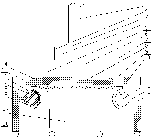
[0033] Embodiment one, such as figure 1 As shown, the present invention provides a kind of anti-falling infusion stand for hospital care infusion, comprising an annular support 13, a plurality of walking wheels 20 are arranged at the bottom of the support 13, a top plate 10 is arranged at the top of the support 13, and the support 13 Several cross arms 12 are arranged inside, and the cross arms 12 point to the center of the plane circle where the support 13 is located. The ends of the cross arms 12 are horizontally provided with an annular track 11, and a center of gravity adjustment mechanism is arranged on the track 11. The center of the top plate 10 is provided with an installation cylinder 3, and a telescopic infusion stand 1 is arranged inside the installation cylinder 3, and an inclination monitoring mechanism is arranged on the outside of the installation cylinder 3, and the center of gravity adjustment mechanism and the inclination monitoring mechanism are arranged on the...
Embodiment 2
[0039] Embodiment two, such as figure 1 Shown: The difference from Embodiment 1 is that the center of gravity adjustment mechanism includes a first slide rail 17 provided on the upper surface of the track 11 and a second slide rail 19 provided on the lower surface, the first slide rail 17 and the second slide rail 19 The two sliding rails 19 cooperate with each other, and the inner surface of the rail 11 is provided with a semicircular ring-shaped sliding sleeve 15, the sliding sleeve 15 matches the structure of the rail 11, and the upper end of the sliding sleeve 15 corresponds to the The first sliding rail 17 is provided with a first sliding bar 16, and the lower end of the sliding sleeve 15 is provided with a second sliding bar 18 corresponding to the second sliding rail 19. The mechanism is connected by transmission, and a counterweight 24 is arranged on the lower part of the sliding sleeve 15 .
[0040] The first sliding rail and the second sliding rail cooperate with th...
Embodiment 3
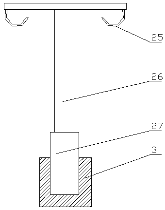
[0041] Embodiment three, such as figure 1 with 2 As shown, the difference from Embodiment 1 is that the driving mechanism includes a mounting slot 8 provided on the top plate 10, and a driving motor 6 is arranged in the mounting slot 8, and the driving motor 6 and the control mechanism 5 signal Connected, the output shaft of the drive motor 6 is provided with a drive gear 7, the top plate 10 is provided with a transmission hole 9 corresponding to the drive gear 7, and the upper end of the sliding sleeve 15 is provided with a drive gear that matches the drive gear 7 14.
[0042] The installation groove is used to fix the driving mechanism. The driving mechanism adopts a motor, and its rotation is controlled by the control mechanism. The driving gear cooperates with the transmission teeth set on the sliding sleeve, and the sliding sleeve can be driven by the motor to rotate, thereby realizing the movement of the counterweight. Purpose.
[0043] The drive motor 6 is a servo mo...
PUM
 Abstract
Description
Claims
Application Information
 - R&D
- Intellectual Property
- Life Sciences
- Materials
- Tech Scout
- Unparalleled Data Quality
- Higher Quality Content
- 60% Fewer Hallucinations
Browse by: Latest US Patents, China's latest patents, Technical Efficacy Thesaurus, Application Domain, Technology Topic, Popular Technical Reports.
© 2025 PatSnap. All rights reserved.Legal|Privacy policy|Modern Slavery Act Transparency Statement|Sitemap|About US| Contact US: help@patsnap.com


