Tracking and positioning code disc

A technology of tracking and positioning and code disc, which is applied in the direction of transportation and packaging, conveyor objects, etc., and can solve the problems of easy loosening of bolts, affecting positioning and tracking, and failure of the bolt sensor switch to sense

CN108045924AInactive Publication Date: 2018-05-18AUTOMOTIVE ENG CORP
3 Cites 0 Cited by

Patent Information

Authority / Receiving Office
CN · China
Current Assignee / Owner
Publication Date
2018-05-18
Estimated Expiration
Not applicable · inactive patent

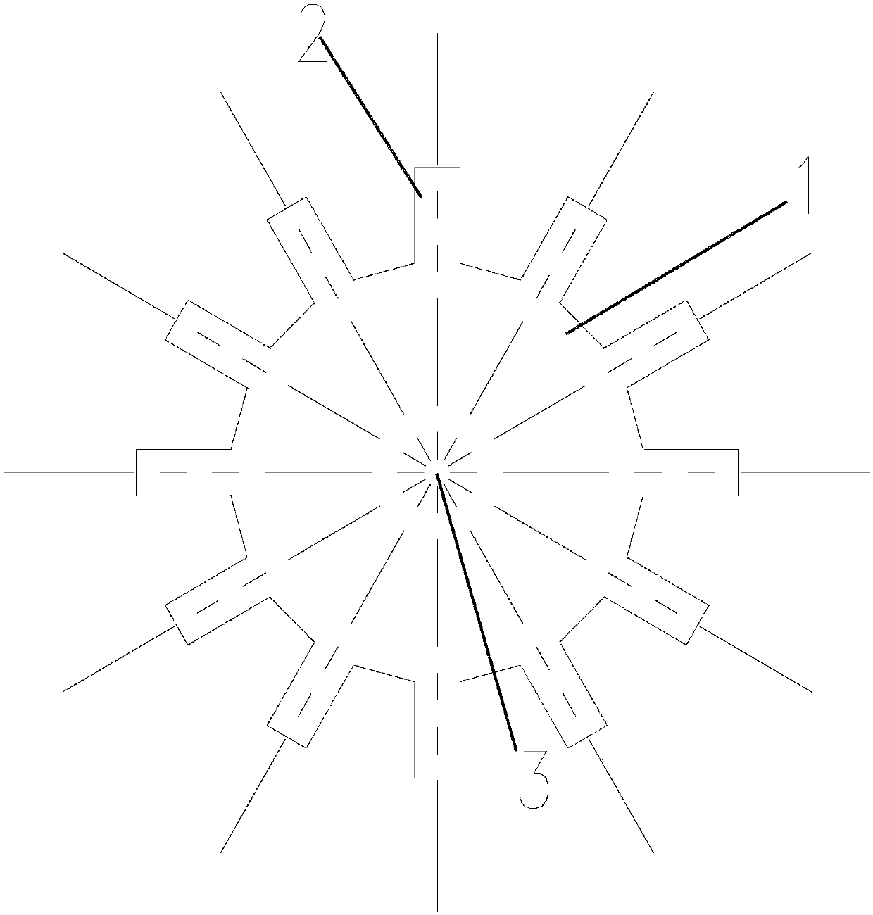
Smart Images

  • Figure 1
    Figure 1
  • Figure 2
    Figure 2
Patent Text Reader

Abstract

The invention discloses a tracking and positioning code disc. The tracking and positioning code disc comprises a round sheet-shaped code disc body, and multiple positioning detection teeth which are uniformly distributed and are integrally formed on the outer circumferential surface of the code plate body, wherein the heights of the multiple positioning detection teeth are consistent with one another; and a mounting shaft hole is formed in the center of the coded disc body. According to the tracking and positioning code disc, workpieces with sawteeth on a whole steel plate can be cut by adopting a numerical control machine tool, meanwhile, installation and debugging are convenient, the positioning and tracking effect is good, and the defects of a bolt type code disc are overcome.
Need to check novelty before this filing date? Find Prior Art

Description

technical field

[0001] The invention relates to the technical field of workpiece positioning, in particular to a tracking and positioning code disc. Background technique

[0002] On the process belt, a code disc is generally installed on the motor shaft, combined with an inductive switch located on the outside of the code disc to realize the positioning and tracking of the workpiece in transmission through pulse counting. The current code disc generally adopts a bolt type code disc, that is, a plurality of bolts are evenly spaced along a circle on the surface of the disc, and the height of the installed bolts must be consistent. If the installed bolts are not on the same plane, there are some bolt induction switches. The problem is that the sensor cannot be sensed, and the bolts are easy to loosen during use, which affects accurate positioning and tracking. Contents of the invention

[0003] The object of the present invention is to provide a tracking and positioning code...

Examples

Embodiment Construction

[0011] The present invention will be described in further detail below in conjunction with the accompanying drawings and specific embodiments. It should be understood that the specific embodiments described here are only used to explain the present invention, not to limit the present invention.

[0012] see figure 1 As shown, a tracking and positioning code wheel includes a circular sheet-shaped code wheel body 1, and a plurality of positioning detection teeth 2 evenly arranged are formed in one piece on the outer circumference of the code wheel body. The heights of the positioning detection teeth are consistent; the center of the code disc body has a shaft hole 3 for installation.

[0013] Preferably, the detection and positioning teeth are rectangular. Of course, other consistent shape structures of convex and concave are also possible.

[0014] The thickness of the code wheel body is consistent with that of the positioning detection teeth.

[0015] The widths of the pos...