Supercharge Your Innovation With Domain-Expert AI Agents!

Locking handle mechanism

A technology for locking handles and handle heads, which is applied in the field of locking handles of large-caliber weapons, can solve problems such as easy falling off, and achieve the effects of reliable fixing, simple structure and convenient operation.

Active Publication Date: 2018-05-18
CHONGQING JIANSHE IND GRP +1
View PDF3 Cites 0 Cited by
  • Summary
  • Abstract
  • Description
  • Claims
  • Application Information

AI Technical Summary

Problems solved by technology

[0004] In order to solve the problem that the existing locking handle mechanism is easy to fall off and automatically lock in actual combat, the present invention provides a locking handle mechanism with reliable fixing and convenient positioning functions

Method used


Image

  • Locking handle mechanism
  • Locking handle mechanism

Examples


Embodiment Construction

[0013] The present invention will be further described below in conjunction with accompanying drawing.

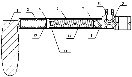
[0014] See figure 1 , figure 2 , the locking handle mechanism of the present invention includes a handle 1, a pull rod 2, a handle sleeve 3, a positioning seat 4, a handle head 5, a locking screw 6, a positioning top 7, a top block pin 8, a fixed rod pin 9, a positioning top Rod 10, fixed rod 11, return spring 12, reset top block 13.

[0015] The handle 1 is connected to the pull rod 2 by welding, the handle sleeve 3 is connected to the handle head 5 by welding, the positioning ejector rod 10 is loaded into the handle head 5, and the ejector block 13, the ejector block 13, Back-moving spring 12 and fixed rod 11 are packed in pull rod 2 and handle sleeve 3.

[0016] Positioning plug 7 The positioning plug 7 is installed on the positioning seat 4, and is ejected outward under the action of the inner spring force of the positioning seat 4, and the positioning plug 7 is pus...


PUM


Abstract

The invention discloses a locking handle mechanism of a large-caliber weapon. The locking handle mechanism of the large-caliber weapon comprises a holding handle, a pull rod, a handle sleeve, a locating seat, a handle head, a locking threaded rod, a locating ejector head, an ejector block pin, a fixing rod pin, a locating ejector rod, a fixing rod, a reset spring and a reset ejector block. According to the locking handle mechanism, the fixing rod which is under the action of spring force is adopted to fix the locking handle in the limited space of the handle sleeve, the ejector rod in a locking head is ejected into a groove of the fixing rod through the ejector block at the specific position so that the locating function can be achieved; and only when external force pulls the groove of thefixing rod out of the action range of the ejector rod, the ejector rod can eject out the ejection block, and the locking handle can eliminate the locating function. The locking handle mechanism of the large-caliber weapon is simple in structure, convenient to operate and reliable in fixation.

Description

technical field [0001] The invention relates to a locking mechanism, in particular to a locking handle of a large-caliber weapon. Background technique [0002] Due to the high quality of the entire weapon system of conventional large-caliber weapons, in order to improve the ergonomics during daily training and use, a locking mechanism is designed in height and orientation. The general locking mechanism has only one fixed circlip. After repeated use for a long time, the circlip is easy to fail, causing the locking mechanism to be unable to be effectively fixed, and often falls off during use, which affects the performance of the weapon system. [0003] In the process of actual combat shooting of conventional large-caliber weapons, in order to effectively aim and kill the target, the locking mechanisms of height and azimuth are all in the open mode, and the weapon system is constantly aiming and shooting during the shooting process. Automatic locking often occurs under freque...

Claims


Application Information

Patent Timeline
Patent Type & Authority Applications(China)
IPC IPC(8): F41A17/00
Inventor 何毳张子军林文军黄歌德段雪峰何伟范兴建张志鹏
Owner CHONGQING JIANSHE IND GRP
Features
  • R&D
  • Intellectual Property
  • Life Sciences
  • Materials
  • Tech Scout
  • Unparalleled Data Quality
  • Higher Quality Content
  • 60% Fewer Hallucinations
Learn More