
Novel garbage disposal device

A garbage disposal device, a new type of technology, applied in the direction of stamping machines, presses, manufacturing tools, etc., can solve the problems of reduced efficiency, large energy consumption, small action surface, etc., to prolong service life, improve safety, and improve stability Effect

Inactive Publication Date: 2018-05-25
方安定
View PDF0 Cites 0 Cited by
  • Summary
  • Abstract
  • Description
  • Claims
  • Application Information

AI Technical Summary

Problems solved by technology

[0002] Nowadays, municipal solid waste is uniformly processed by waste treatment plants. Because many wastes are in a fluffy state before treatment, they occupy a large area and are not easy to handle. Therefore, it is necessary to crush the waste. Traditional waste compaction is done manually. Mobile vibrating garbage compactors or large-scale hydraulic garbage compactors, this kind of garbage compaction method is slow, has a small action area, and consumes a lot of energy, wastes energy and has a low environmental protection factor, which greatly reduces the efficiency of compaction and increases reduce the cost of rubbish rolling

Method used


Image

  • Novel garbage disposal device
  • Novel garbage disposal device
  • Novel garbage disposal device

Examples


Embodiment Construction

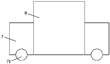
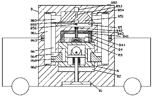
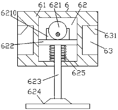
[0017] Such as Figure 1-Figure 6 As shown, a new type of garbage disposal device of the present invention includes a traveling vehicle body 7 and a seat body 8 installed in the traveling vehicle body 7. 8 A sinking groove 81 is provided in the end surface of the bottom, and a lifting chamber 82 is provided in the seat body 8 on the upper side of the sinking groove 81, and a compression device 6 is movably connected in the lifting chamber 82, and the The compression device 6 includes a lifting frame 61 and a compression element arranged in the lifting frame 61. The left and right sides of the lifting frame 61 are equally provided with recessed grooves 63 in the end faces, and the inner top of each of the recessed grooves 63 The walls are all fixed with a first hypotenuse block 631, and the midpoint position in the top wall of the lifting chamber 82 is provided with a first spring pressing member 83 that touches the top end surface of the lifting frame 61. A locking device is ...


PUM


Abstract

The invention discloses a novel garbage disposal device. The garbage disposal device comprises a traveling vehicle body and a seat body mounted in the traveling vehicle body; traveling wheels are mounted on the bottom end surface of the traveling vehicle body in a rolling manner; a sinking groove is formed in the bottom end surface of the seat body; a rising and falling cavity is formed in the seat body above the sinking groove; a compression device is connected in the rising and falling cavity in a movably matched manner and comprises a rising and falling frame and a compression element arranged in the rising and falling frame; concave grooves are equally formed in the end surfaces of the left side and the right side of the rising and falling frame; a first inclined-edge block is fixedlyarranged on the inner top wall of each concave groove; a first elastic pressing piece making contact with the top end surface of the rising and falling frame is arranged at the central point in the inner top wall of the rising and falling cavity; a locking connection device is arranged in the inner wall body of the seat body on the upper side of the first elastic pressing piece; and a pushing extruding device is arranged on the inner wall body of the seat body on the upper side of the locking connection device. The garbage disposal device is simple in structure and convenient to operate, the safety is improved, the service life of the garbage disposal device is further prolonged, and the compression stability is improved.

Description

technical field [0001] The invention relates to the technical field of garbage treatment, in particular to a novel garbage treatment device. Background technique [0002] Nowadays, municipal solid waste is uniformly processed by waste treatment plants. Because many wastes are in a fluffy state before treatment, they occupy a large area and are not easy to handle. Therefore, it is necessary to crush the waste. Traditional waste compaction is done manually. Mobile vibrating garbage compactors or large-scale hydraulic garbage compactors, this kind of garbage compaction method is slow, has a small action area, and consumes a lot of energy, wastes energy and has a low environmental protection factor, which greatly reduces the efficiency of compaction and increases Reduced the cost of rubbish rolling. Contents of the invention [0003] The technical problem to be solved by the present invention is to provide a new type of garbage disposal device, which can solve the above-menti...

Claims


Application Information

Patent Timeline
Patent Type & Authority Applications(China)
IPC IPC(8): B30B1/26B30B15/00
CPCB30B1/26B30B15/00
Inventor 方安定
Owner 方安定
Learn More