A new type of cutting machine

A cutting machine, a new technology, applied in the direction of shearing device, cutting tool for shearing device, metal processing equipment, etc., can solve the problems of low cutting efficiency, hidden safety hazards, high operation risk, etc., achieve simple structure, improve cutting The effect of efficiency, ease of installation and removal

Active Publication Date: 2019-04-12
唐山森阳精密机械制造有限公司
View PDF5 Cites 0 Cited by
  • Summary
  • Abstract
  • Description
  • Claims
  • Application Information

AI Technical Summary

Problems solved by technology

[0002] When cutting tubular metal parts, the traditional method is generally to cut by workers holding a new type of cutting machine. The operation risk is high and there are potential safety hazards. In addition, due to the inaccurate manual control, the cutting will be skewed, and the scrap rate is high. Some Fully automatic new cutting machines are generally equipped with only one cutting head, and the cutting efficiency is low

Method used


Image

  • A new type of cutting machine
  • A new type of cutting machine
  • A new type of cutting machine

Examples


Embodiment Construction

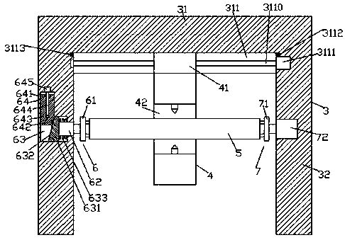
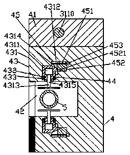
[0021] Such as figure 1 , figure 2 and image 3 As shown, a new type of cutting machine of the present invention includes a body 3 composed of a transverse beam 31 and support feet 32 ​​fixed on the left and right sides of the transverse beam 31. The bottom end surface of the transverse beam 31 is provided with a sliding Groove 311, the sliding groove 311 is provided with a first screw rod 3110 extending left and right, the first screw rod 3110 is connected with a sliding block 41 with an inner thread, and the bottom of the sliding block 41 is provided with Cutting device 4, the front end of the cutting device 4 is provided with a recessed groove 42, and the cutting device 4 on both sides of the recessed groove 42 is provided with a first sliding cavity 43 correspondingly, and the first sliding cavity 43 On the side away from the concave groove 42, there is a second sliding cavity 45 extending to the right and interspersed with each other. The second sliding cavity 45 is pr...


PUM


Abstract

The invention discloses a novel cutting machine. The novel cutting machine comprises a machine body, wherein the machine body is formed by a transverse beam and supporting legs fixed at the bottoms ofthe left side and the right side of the transverse beam. A sliding groove is formed in the end surface of the bottom of the transverse beam, the sliding groove is provided with a first screw rod which is arranged in a left-and-right extending mode, a sliding block is connected with the inner screw type of the first screw rod in a matched mode, and a cutting device is arranged at the bottom of thesliding block. A concave groove is formed in the front end of the cutting device, a first sliding cavity is arranged in the cutting device at the upper side and the lower side of the concave groove in a matched mode, a second sliding cavity extending towards the right side is formed in the side, far away from the sunken groove, of the first sliding cavity, a second screw rod which is arranged ina left-and-right extension mode is arranged in the second sliding cavity, the second screw rod is in screw-type fit connection with a pushing and extruding block, a limiting block is arranged on the side, close to the sunken groove, of the inner wall of the right side of the first sliding cavity, and an upper sliding block and a lower sliding block are arranged in the first sliding cavity in a sliding mode in a sliding mode. The novel cutting device is simple in structure, convenient to mount and dismount, high in cutting efficiency and capable of meeting the cutting work of metal parts with different diameters.

Description

technical field [0001] The invention relates to the technical field of cutting, in particular to a novel cutting machine. Background technique [0002] When cutting tubular metal parts, the traditional method is generally to cut by workers holding a new type of cutting machine. The operation risk is high and there are potential safety hazards. In addition, due to the inaccurate manual control, the cutting will be skewed, and the scrap rate is high. Some Fully automatic new cutting machines are generally equipped with only one cutting head, and the cutting efficiency is low. Contents of the invention [0003] The technical problem to be solved by the present invention is to provide a new type of cutting machine, which can solve the above-mentioned problems in the prior art. [0004] The present invention is achieved through the following technical proposals: A novel cutting machine of the present invention includes a body composed of a transverse beam and support feet fixe...

Claims


Application Information

Patent Timeline
Patent Type & Authority Patents(China)
IPC IPC(8): B23D33/02B23D35/00
CPCB23D33/02B23D35/00
Inventor 方余
Owner 唐山森阳精密机械制造有限公司
Why Eureka
Try Eureka