Anti-icing device for crankcase, crankcase ventilating system, engine and automobile

A crankcase ventilation and anti-icing technology, applied in crankcase ventilation, engine components, machines/engines, etc., can solve problems such as oil leakage, engine failure, and exhaust gas that cannot be removed in time

Inactive Publication Date: 2018-05-25
SAIC MOTOR
View PDF5 Cites 7 Cited by
  • Summary
  • Abstract
  • Description
  • Claims
  • Application Information

AI Technical Summary

Problems solved by technology

[0004] Especially at the connection between the crankcase ventilation pipe and the intake system, the exhaust gas meets a large amount of cold air and is cooled rapidly, and it is easy to condense into ice at the front end of the joint, which gradually accumulates over time; The joints of the system are completely blocked, resulting in the failure of exhaust gas to be removed in time, the pressure in the crankcase rises sharply, the oil seal rushes out, and the engine oil leaks rapidly, eventually causing the engine to fail to work and the vehicle to break down

Method used


Image

  • Anti-icing device for crankcase, crankcase ventilating system, engine and automobile
  • Anti-icing device for crankcase, crankcase ventilating system, engine and automobile
  • Anti-icing device for crankcase, crankcase ventilating system, engine and automobile

Examples


Embodiment 1

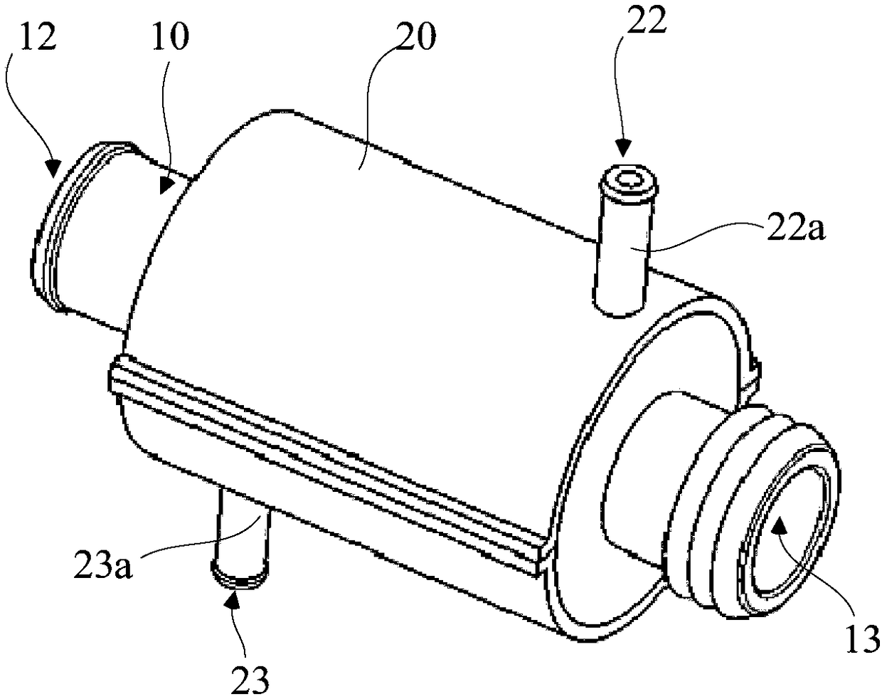
[0045] The embodiment of the present invention provides an anti-icing device for a crankcase, reference image 3 with Figure 4 , The anti-icing device includes: a first channel 11 for gas circulation. In this embodiment, the first channel 11 is for the circulation of crankcase exhaust gas; the shape of the first channel 11 is not limited, and can be cylindrical, rectangular or Cube-shaped. In this embodiment, the first channel 11 is cylindrical. Along the length direction of the first channel 11, both ends of the first channel 11 in the length direction have a first connection port 12 and a second connection port 13, and the first connection port 12 is used for Connect with crankcase ventilation pipe 40 (reference Image 6 ), the second connection port 13 is used to communicate with the air intake system.

[0046] In this embodiment, the first connection port 12 and the second connection port 13 are located at both ends of the length direction of the first passage 11. In other e...

Embodiment 2

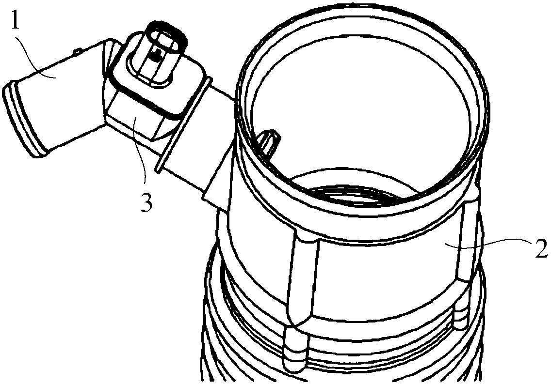
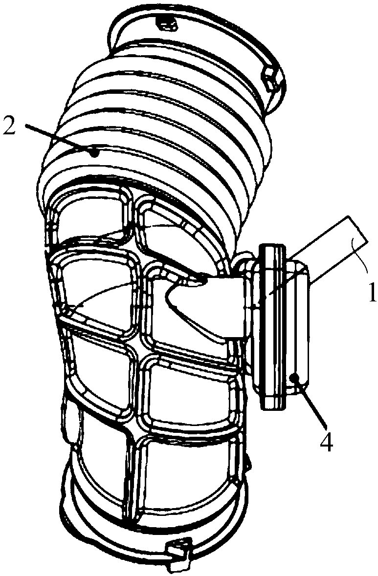
[0062] reference Image 6 And combine Figure 5 As shown, this embodiment provides a crankcase ventilation system, including: the anti-icing device for the crankcase in the first embodiment; a crankcase ventilation pipe 40 connected to the first connecting port 12, Image 6 It can be seen that the boss 30 on the outer peripheral surface of the first connecting port 12 is in interference fit with the inner wall of the crankcase ventilation pipe 40. The material of the crankcase ventilation pipe 40 is plastic or rubber, and the boss 30 will squeeze the crankcase ventilation pipe 40. The inner wall makes the boss 30 and the inner wall of the crankcase ventilation pipe 40 tightly connected together, and the sealing performance is good.

[0063] It also includes an air intake pipe 50, which is connected to the second connection port 13. In this embodiment, an air filter is provided on the air intake pipe 50, and a third connection port is provided between the air filter and the air inta...

Embodiment 3

[0069] The thermal fluid source in this embodiment is different from the thermal fluid source in the second embodiment, and the rest are the same. In this embodiment, reference Figure 7 And combine Figure 5 As shown, the hot fluid source further includes: a supercharger 80 arranged on the intake pipe 50; an intercooler 90 is also arranged on the intake pipe 50, and the supercharger 80 is closer to the intake pipe 50 than the intercooler 90 Air inlet; there is a hot fluid source outlet and a hot fluid source inlet between the supercharger 80 and the intercooler 90. The hot fluid source outlet is closer to the supercharger 80 than the hot fluid source inlet; the hot fluid inlet 22 passes through the pipe 81 is connected with the hot fluid source outlet, the boss 30 on the outer peripheral surface of the hot fluid inlet 22 is in interference fit with the pipe 81 to improve the sealing performance; the hot fluid outlet 23 is connected with the hot fluid source inlet through the p...


PUM


Abstract

The invention discloses an anti-icing device for a crankcase, a crankcase ventilating system, an engine and an automobile. The anti-icing device for the crankcase comprises a first channel and a shell. The first channel is provided with a first connector and a second connector. The first connector is used for communicating with a crankcase ventilating pipe, and the second connector is used for communicating with an air inlet system. The shell surrounds the outer surface of the first channel, and the inner wall of the shell and the outer surface of the first channel define a second channel. According to the anti-icing device for the crankcase, the crankcase ventilating system, the engine and the automobile, heat can be transmitted to the first channel when thermal fluid circulates in the second channel, and then crankcase exhaust gas circulating in the first channel can be heated; and after the crankcase exhaust gas is heated, icing cannot happen to the connecting position of the crankcase ventilating pipe and the air inlet system easily, the crankcase ventilating system can operate normally, the engine can also achieve normal operation, and hence the automobile can travel normally.

Description

Technical field [0001] The invention relates to the technical field of automobiles, in particular to an anti-icing device for a crankcase, a crankcase ventilation system, an engine and an automobile. Background technique [0002] When the engine is working, the high-pressure combustible mixture and burned gas in the combustion chamber will more or less leak into the crankcase through the gap between the piston group and the cylinder, causing blow-by. The components of blow-by gas are unburned fuel gas, water vapor and exhaust gas, etc., which will dilute the oil, reduce the performance of the oil, and accelerate the oxidation and deterioration of the oil. Condensation of water vapor in the engine oil will form sludge and block the oil circuit; the acid gas in the exhaust gas mixed into the lubrication system will cause corrosion and accelerated wear of engine parts; blow-by will also cause the pressure of the crankcase to be too high and damage the crankcase Seal, so that the oi...

Claims


Application Information

Patent Timeline
Patent Type & Authority Applications(China)
IPC IPC(8): F01M13/00F01M13/04
CPCF01M13/00F01M13/04F01M2013/0455
Inventor 马鹏王康陈晓霞刘旻
Owner SAIC MOTOR
Why Eureka
Try Eureka