High-efficiency egg stirrer

A masher and a high-efficiency technology, applied in the masher field, can solve the problems of time-consuming, laborious, uneven mashing, etc.

Inactive Publication Date: 2018-05-29
龚春华
View PDF8 Cites 1 Cited by
  • Summary
  • Abstract
  • Description
  • Claims
  • Application Information

AI Technical Summary

Problems solved by technology

[0005] In order to overcome the shortcomings of uneven mashing and time-consuming and labor-intensive manual mashing, the technical problem to be solved by the present invention is to provide a kitchen machine with a wide application range, simple operation, time-saving and labor-saving, thorough and uniform mashing, and high work efficiency. Trick or treat equipment

Method used


Image

  • High-efficiency egg stirrer
  • High-efficiency egg stirrer
  • High-efficiency egg stirrer

Examples


Embodiment 1

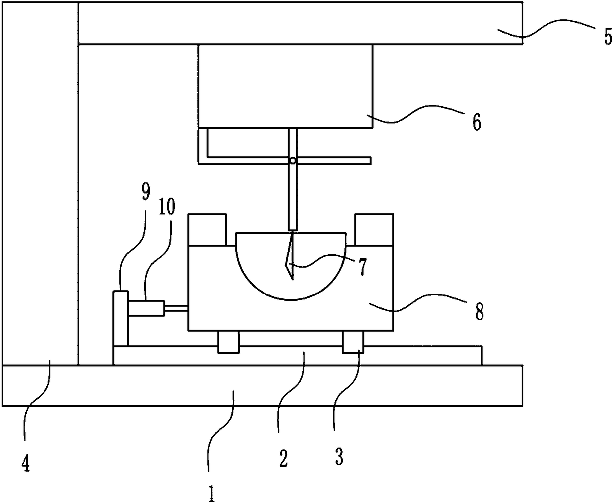
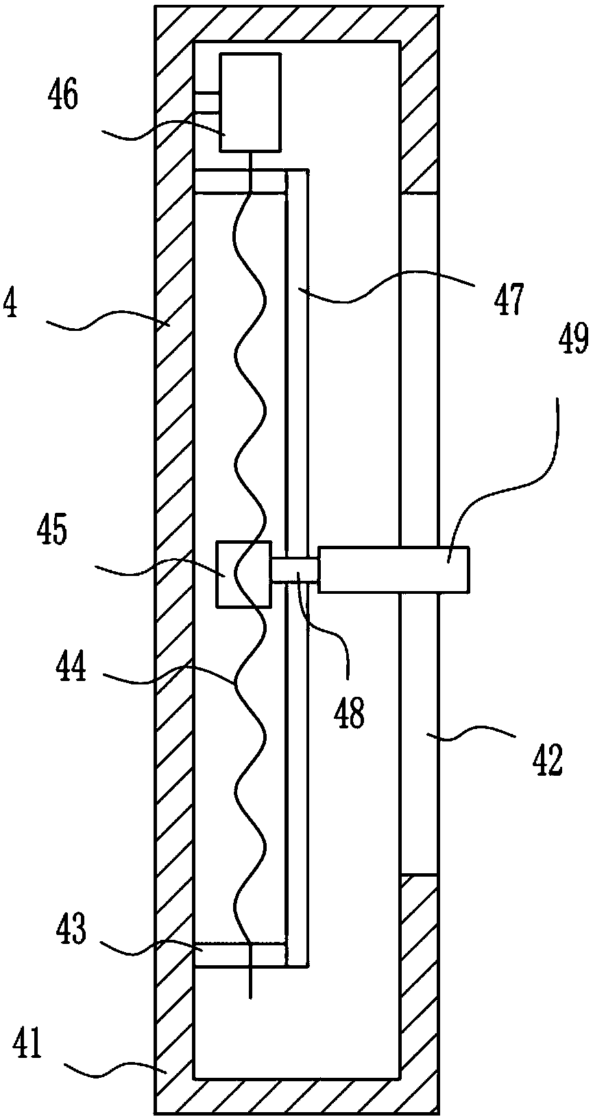
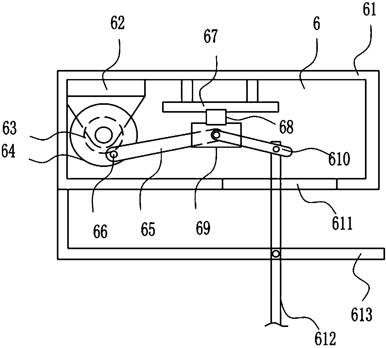
[0037] An efficient masher such as Figure 1-5 As shown, it includes a base 1, a first slide rail 2, a first slider 3, a lifting device 4, a top plate 5, a swinging device 6, a stirring plate 7, a fixing device 8, a fixing plate 9 and an electric push rod 10, and the base 1 The first sliding rail 2 is welded on the right side of the top, and the first sliding block 3 is slidably connected to the first sliding rail 2. The top of the first sliding block 3 is connected with a fixing device 8 by bolt connection. The top of the first sliding rail 2 The left side is welded with a fixed plate 9, and the left side of the fixed plate 9 is connected with an electric push rod 10 by means of bolt connection. The left side is connected with a lifting device 4 by means of bolt connection, the top of the right side of the lifting device 4 is welded with a top plate 5, the middle of the bottom of the top plate 5 is connected with a swing device 6 through a bolt connection, and the bottom of t...

Embodiment 2

[0039] An efficient masher such as Figure 1-5 As shown, it includes a base 1, a first slide rail 2, a first slider 3, a lifting device 4, a top plate 5, a swinging device 6, a stirring plate 7, a fixing device 8, a fixing plate 9 and an electric push rod 10, and the base 1 The first sliding rail 2 is welded on the right side of the top, and the first sliding block 3 is slidably connected to the first sliding rail 2. The top of the first sliding block 3 is connected with a fixing device 8 by bolt connection. The top of the first sliding rail 2 The left side is welded with a fixed plate 9, and the left side of the fixed plate 9 is connected with an electric push rod 10 by means of bolt connection. The left side is connected with a lifting device 4 by means of bolt connection, the top of the right side of the lifting device 4 is welded with a top plate 5, the middle of the bottom of the top plate 5 is connected with a swing device 6 through a bolt connection, and the bottom of t...

Embodiment 3

[0042] An efficient masher such as Figure 1-5 As shown, it includes a base 1, a first slide rail 2, a first slider 3, a lifting device 4, a top plate 5, a swinging device 6, a stirring plate 7, a fixing device 8, a fixing plate 9 and an electric push rod 10, and the base 1 The first sliding rail 2 is welded on the right side of the top, and the first sliding block 3 is slidably connected to the first sliding rail 2. The top of the first sliding block 3 is connected with a fixing device 8 by bolt connection. The top of the first sliding rail 2 The left side is welded with a fixed plate 9, and the left side of the fixed plate 9 is connected with an electric push rod 10 by means of bolt connection. The left side is connected with a lifting device 4 by means of bolt connection, the top of the right side of the lifting device 4 is welded with a top plate 5, the middle of the bottom of the top plate 5 is connected with a swing device 6 through a bolt connection, and the bottom of t...


PUM


Abstract

The invention relates to an egg stirring tool, in particular to a high-efficiency egg stirrer. According to the technical aims, egg stirring equipment for a kitchen is wide in application range, easyto operate, even and complete in stirring and high in working efficiency and saves time and labor. In order to achieve the technical aims, the high-efficiency egg stirrer comprises a base, a first sliding rail, first sliding blocks, a lifting device, a top plate, a swing device and the like; the first sliding rail is welded to the right side of the top of the base, the first sliding blocks are slidingly connected onto the first sliding rail, and a fixing device is connected to the tops of the first sliding blocks through bolts; a fixing plate is welded to the left side of the top of the firstsliding rail, and an electric push rod is connected to the left side of the fixing plate through bolts. According to the high-efficiency egg stirrer, the swing device, the lifting device, the fixing device and an electric push rod are controlled to work, and a second motor is controlled to work.

Description

technical field [0001] The invention relates to an egg stirring tool, in particular to a high-efficiency whisk. Background technique [0002] Eggs are eggs laid by certain land animals, and the embryo is surrounded by a watertight shell. Birds, reptiles, and the mammalian platypus and echidna families all lay eggs. At the right temperature, the eggs will hatch at a certain time, and the larvae will use the horny substance above the mouth to open the eggshell and break out of the shell. Eggs are rich in nutrition, cheap, and can be made into various delicacies such as stewed eggs, tea eggs, cakes, etc., so they have been regarded as the best source of nutritional supplements since ancient times. [0003] Generally, beating is done manually with a mashing device. Manual mashing has the disadvantages of uneven mashing and time-consuming and laborious efforts. Therefore, there is an urgent need to develop a kitchen mashing equipment that is simple to operate, saves time and ef...

Claims


Application Information

Patent Timeline
Patent Type & Authority Applications(China)
IPC IPC(8): A47J43/10
CPCA47J43/10
Inventor 不公告发明人
Owner 龚春华
Why Eureka
Try Eureka