A round shell making equipment for LED downlight production
A LED downlight and circular technology, which is applied to other manufacturing equipment/tools, manufacturing tools, etc., can solve the problems of low work efficiency, low precision, and low safety of long iron sheets, and achieve consistent length, Effects of improving safety and improving work efficiency
- Summary
- Abstract
- Description
- Claims
- Application Information
AI Technical Summary
Problems solved by technology
Method used
Image
Examples
Embodiment 1
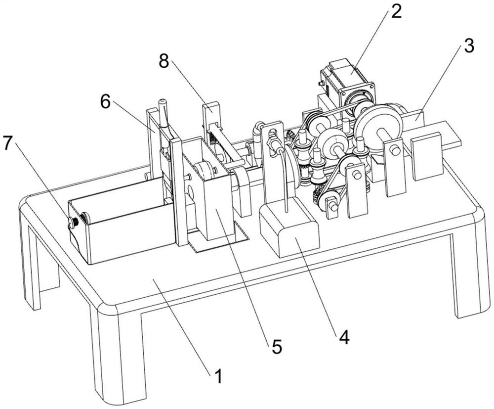
[0076] A round shell making equipment for LED downlight production, such as figure 1 As shown, it includes worktable 1, servo motor 2, bending mechanism 3, welding mechanism 4, grinding mechanism 5 and cutting mechanism 6. The right part of the rear side of the top of worktable 1 is provided with a servo motor 2, and the right side of the top of worktable 1 is provided with a servo motor 2. A bending mechanism 3 is provided between the output shaft of the servo motor 2, a welding mechanism 4 is provided in the middle of the front side of the top of the worktable 1, a grinding mechanism 5 is provided on the left side of the top of the worktable 1, and a cutting mechanism is provided on the left side of the top of the worktable 1. 6.
[0077] When people need to make the LED downlight shell, first put the long iron sheet from the right side of the bending mechanism 3, then start the servo motor 2, the output shaft of the servo motor 2 drives the bending mechanism 3 to transmit t...
Embodiment 2
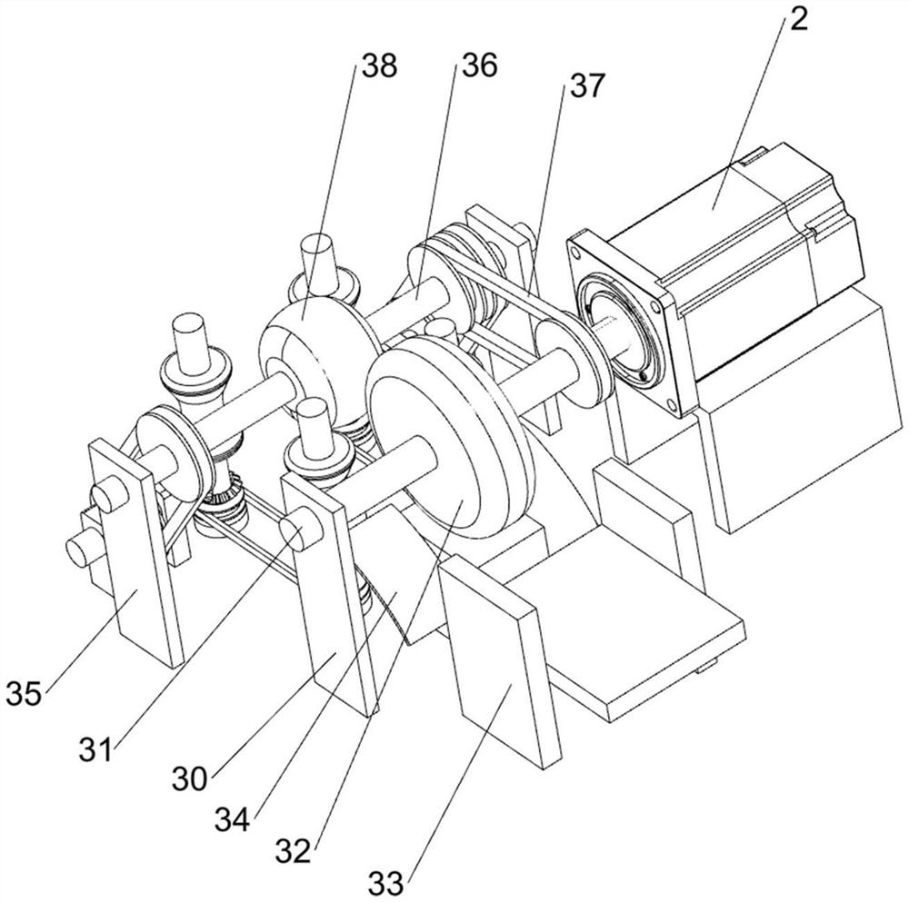
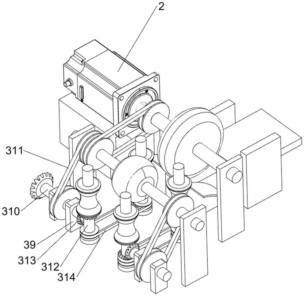
[0079] On the basis of Example 1, as figure 2 , image 3 and Figure 4 As shown, the bending mechanism 3 includes a first support plate 30, a rotating shaft 31, a limit wheel 32, a feeding rack 33, a bending assembly 34, a second support plate 35, a rotating rod 36, a first pulley assembly 37, The rotating wheel 38, the first support block 39, the transmission shaft 310, the second pulley assembly 311, the stopper 312, the first bevel gear assembly 313 and the third pulley assembly 314, the front right side of the top of the workbench 1 is provided with a first The support plate 30, the upper part of the first support plate 30 is rotatably provided with a rotating shaft 31, the rear end of the rotating shaft 31 is connected with the output shaft of the servo motor 2, the middle of the rotating shaft 31 is provided with a limit wheel 32, and the middle of the top right side of the workbench 1 is provided with The feeding rack 33 is located on the right side of the limit whee...
Embodiment 3
[0086] On the basis of Example 2, as Figure 5 and Image 6 As shown, the cutting mechanism 6 includes a support frame 60, an electric push rod 61, a cutting blade 62, a cushion block 63 and a blanking box 64, a support frame 60 is provided in the middle of the left side of the top of the worktable 1, and a support frame 60 is provided in the middle of the upper part of the support frame 60. The electric push rod 61, the bottom of the electric push rod 61 is provided with a cutting blade 62, the middle of the top left of the workbench 1 is provided with a pad 63, the pad 63 is located under the support frame 60, the right side of the pad 63 and the left side of the dust box 54 For connection, a blanking box 64 is arranged in the middle of the left side of the top of the workbench 1 , and the right side of the blanking box 64 is connected with the cushion block 63 .
[0087] The grinding wheel 56 grinds the welding marks on the cylindrical iron sheet, and the limit wheel 32 co...
PUM
 Abstract
Description
Claims
Application Information
 - R&D
- Intellectual Property
- Life Sciences
- Materials
- Tech Scout
- Unparalleled Data Quality
- Higher Quality Content
- 60% Fewer Hallucinations
Browse by: Latest US Patents, China's latest patents, Technical Efficacy Thesaurus, Application Domain, Technology Topic, Popular Technical Reports.
© 2025 PatSnap. All rights reserved.Legal|Privacy policy|Modern Slavery Act Transparency Statement|Sitemap|About US| Contact US: help@patsnap.com


