Suction filtering tank and suction filtering method

A filter tank and filter plate technology, applied in the field of chemical production suction filtration treatment, can solve problems such as material waste, and achieve the effects of improving recovery rate, preventing falling off, and uniform air pressure

Inactive Publication Date: 2018-05-29
瓜州伊特科技有限公司
View PDF5 Cites 2 Cited by
  • Summary
  • Abstract
  • Description
  • Claims
  • Application Information

AI Technical Summary

Problems solved by technology

This patent is the same as the existing suction filter tank, which only has one layer of filtration, and there is a waste of materials

Method used


Image

  • Suction filtering tank and suction filtering method
  • Suction filtering tank and suction filtering method

Examples


Embodiment Construction

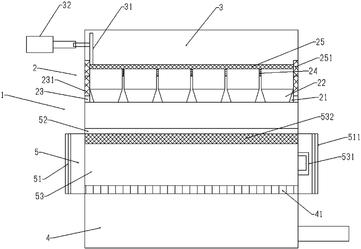
[0028] Such as Figure 1-Figure 2 As shown, a suction filter tank includes a rectangular tank body 1 with an upward opening, a filter layer 2 is arranged in the rectangular tank body 1, a material tank 3 is arranged above the filter layer 2, and a suction filter chamber is arranged below the filter layer 2 4. The filter layer 2 includes a filter plate frame 21 whose edge is fixedly connected to the side wall of the rectangular tank body 1. The filter plate frame 21 is provided with a number of filter plate holes 22 for placing filter plates. The filter plate holes 22 are arranged from top to bottom It is divided into a straight section for placing the filter plate and a tapered section whose inner diameter decreases from top to bottom. The upper end of the straight section of the filter plate hole 22 is provided with a filling rubber strip 24, and the connection between the rectangular tank body 1 and the filter plate holder 21 is along the circumference. There is a slot 231 i...


PUM


Abstract

The invention belongs to the technical field of suction filtering treatment in chemical production, and particularly relates to a suction filtering tank and a suction filtering method. The suction filtering tank comprises a rectangular tank body with an upward opening, a filtering layer is arranged in the rectangular tank body, a material groove is formed in the upper portion of the filtering layer, a suction filtering cavity is formed in the lower portion of the filtering layer, the filtering layer comprises a filtering plate frame with one edge fixedly connected with the side wall of the rectangular tank body, a plurality of filtering plate holes for placing filtering plates are formed in the filtering plate frame, each filtering plate hole comprises a straight section for placing the filtering plates and a conical section with the inner diameter gradually decreased from top to bottom sequentially from top to bottom, a filling rubber strip is arranged at the upper end of the straightsection of each filtering plate hole, and a clamping seam is formed at the joint of the rectangular tank body and the filtering plate frame along the circumferential direction. The filtering layer further comprises a stainless steel filter screen covering the filtering plate frame, and an edge filter screen matched with the clamping seam is connected at the edge of the stainless steel filter screen. The suction filtering tank and the suction filtering method can realize multiple times of filtering, can increase material recovery rate and facilitate material fetching.

Description

technical field [0001] The invention belongs to the technical field of suction filtration treatment in chemical production, and in particular relates to a suction filtration tank and a suction filtration method. Background technique [0002] Vacuum suction filtration is the use of air negative pressure to filter materials to separate solids and liquids. The existing vacuum suction filtration is mostly one-time suction filtration, and when the suction filtration tank is large, workers need to shovel the material out of the suction filtration tank ,Time-consuming. [0003] The patent is an open suction filter tank for the production of 1,2-diphenoxyethane (notification number is CN205435108U), which discloses an open suction filter tank for the production of 1,2-diphenoxyethane The filter tank is composed of multiple parts. The suction filter tank includes: suction filter tank body, support legs, foundation feet, filter plate baffle, filter plate, filter cloth, lifting ring, ...

Claims


Application Information

Patent Timeline
Patent Type & Authority Applications(China)
IPC IPC(8): B01D29/03B01D29/58B01D29/96B01D29/82B01D29/84
CPCB01D29/03B01D29/58B01D29/82B01D29/843B01D29/96
Inventor 王国强楼建华石成相
Owner 瓜州伊特科技有限公司
Why Eureka
Try Eureka