Convenient welding device

A welding device and a convenient technology, applied in the parts, auxiliary devices, coupling devices and other directions of the connecting device, can solve the problems of shortened service life of the welding machine, electric shock accidents of staff, complicated structure of power supply equipment, etc., and achieve safe and stable power supply. , The effect of stable and safe power supply, safe and reliable power supply

Inactive Publication Date: 2018-05-29
晋江双吉装饰工程有限公司
View PDF0 Cites 0 Cited by
  • Summary
  • Abstract
  • Description
  • Claims
  • Application Information

AI Technical Summary

Problems solved by technology

[0002] The use of the welding machine is inseparable from the power supply equipment. When using the traditional welding machine, it is necessary to insert the electric connector of the welding machine into the power supply equipment for power consumption. When the electric connector is inserted into the power supply equipment for power supply, Since the electrical connection slot of the traditional power supply equipment is directly connected to the power supply and is always in the energized state, when the staff does not operate properly, it is easy to cause an electric shock accident to the staff when plugging and unplugging the electrical connector. In addition, the power cord of the welding machine It usually has a certain length. When the welding machine is in use, the power cord of the welding machine is usually scattered around the power supply equipment. When someone accidentally kicks and touches the power cord by mistake, the electrical connector will be separated from the power supply equipment. This phenomenon will not only cause damage to the power cord, but also shorten the service life of the welding machine. In addition, the structure of the power supply equipment of some welding machines is very complicated. The power supply equipment, these power supply equipment need to be powered through the power supply before they can control the operation, which will cause a waste of power resources

Method used


Image

  • Convenient welding device
  • Convenient welding device
  • Convenient welding device

Examples


Embodiment Construction

[0026] The preferred embodiments of the present invention will be described in detail below in conjunction with the accompanying drawings, so that the advantages and features of the present invention can be more easily understood by those skilled in the art, so as to define the protection scope of the present invention more clearly.

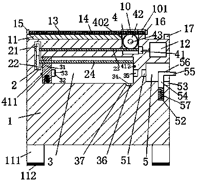
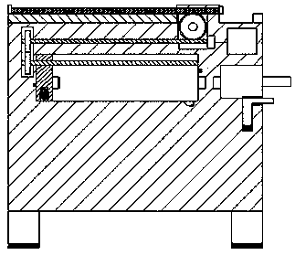
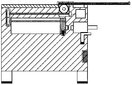
[0027] refer to Figure 1-6A convenient welding device shown includes a frame body 1 and an electrical connector connected to the welding machine. The bottom end of the frame body 1 is provided with a leg 111, and the bottom of the leg 111 is fixedly equipped with a foot pad 112. The top of the frame body 1 is provided with a convex portion 10, the frame body 1 is provided with a first sliding groove 3 extending left and right, and the frame body 1 is provided with a tooth groove 2 at the left end of the first sliding groove 3, so The frame body 1 is also provided with a turbine groove 4 that extends upwards into the convex portion 10, and the co...


PUM


Abstract

The invention discloses a convenient welding device. The device comprises a frame body and an electricity connection head connected with a welding machine, supporting legs are arranged at the bottom end of the frame body, and foot pads are fixedly arranged at the bottom of the supporting legs; a convex part is arranged at the top end of the frame body, a first sliding groove extending leftwards and rightwards is formed in the frame body, and a tooth groove is formed in the left end of the first sliding groove in the frame body; and a turbine groove which extends upwards to the convex part is further arranged in the frame body, a through groove which penetrates left and right and communicates with the turbine groove is formed in the convex part, and a shielding plate is arranged in the through groove in a left-and-right sliding mode. The convenient welding device is simple in overall structure, safe and reliable in power supply, simple and convenient to operate, capable of effectively reducing electric shock accidents caused during the plugging and pulling process of the electricity connection head, capable of guaranteeing life safety of people, furthermore, capable of avoiding thesituation that the welding machine which is electrified is suddenly cut off electricity supply due to mistaken kicking of personnel, capable of effectively prolonging the service life of the welding machine, energy-saving and environmental-friendly and suitable for popularization and use.

Description

technical field [0001] The invention relates to the field of welding, in particular to a convenient welding device. Background technique [0002] The use of the welding machine is inseparable from the power supply equipment. When using the traditional welding machine, it is necessary to insert the electric connector of the welding machine into the power supply equipment for power consumption. When the electric connector is inserted into the power supply equipment for power supply, Since the electrical connection slot of the traditional power supply equipment is directly connected to the power supply and is always in the energized state, when the staff does not operate properly, it is easy to cause an electric shock accident to the staff when plugging and unplugging the electrical connector. In addition, the power cord of the welding machine It usually has a certain length. When the welding machine is in use, the power cord of the welding machine is usually scattered around t...

Claims


Application Information

Patent Timeline
Patent Type & Authority Applications(China)
IPC IPC(8): B23K37/00H01R13/639H01R13/70
CPCB23K37/006H01R13/639H01R13/701
Inventor 林培双何胜利
Owner 晋江双吉装饰工程有限公司
Why Eureka
Try Eureka