Arm frame of an oil cylinder luffing crane

A boom and oil cylinder technology, which is applied in the field of lifting and transportation machinery, can solve the problems of small load-bearing capacity and unreasonable design, and achieve the effects of improving load-bearing capacity, enhancing stability, and enhancing the stress range

Active Publication Date: 2019-11-15
WUHAN MARINE MACHINERY PLANT
View PDF5 Cites 0 Cited by
  • Summary
  • Abstract
  • Description
  • Claims
  • Application Information

AI Technical Summary

Problems solved by technology

[0006] In order to solve the problems of low load-bearing capacity and unreasonable design of the existing oil cylinder luffing jib, the embodiment of the present invention provides an oil cylinder luffing jib jib

Method used


Image

  • Arm frame of an oil cylinder luffing crane
  • Arm frame of an oil cylinder luffing crane
  • Arm frame of an oil cylinder luffing crane

Examples


Embodiment Construction

[0032] In order to make the object, technical solution and advantages of the present invention clearer, the implementation manner of the present invention will be further described in detail below in conjunction with the accompanying drawings.

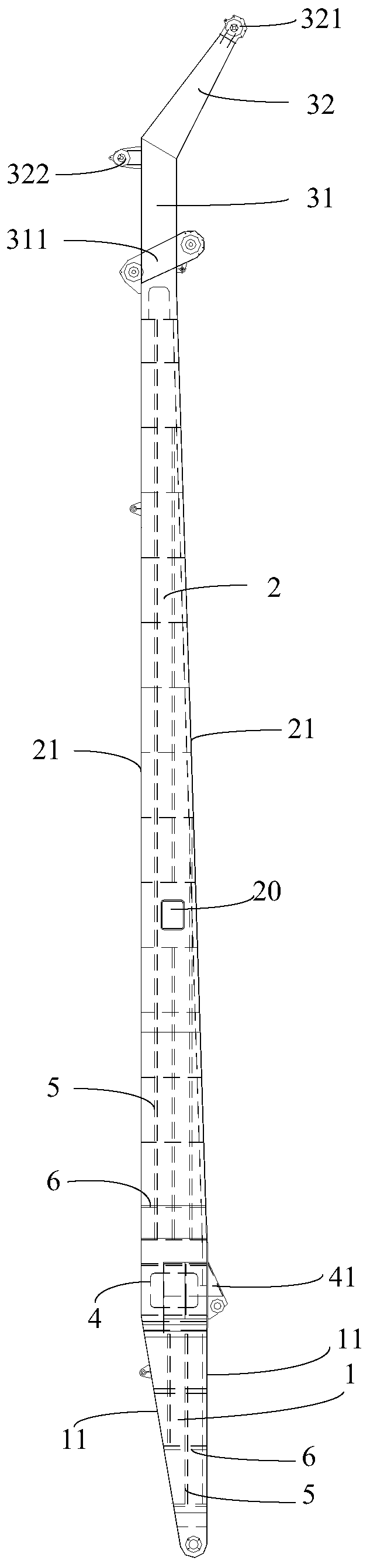
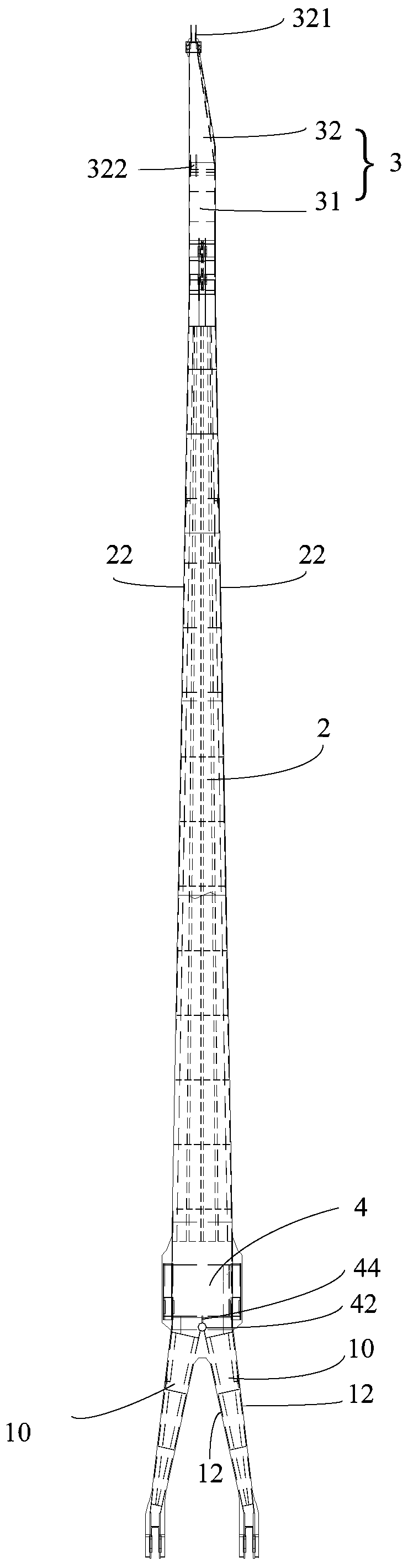
[0033] An embodiment of the present invention provides a jib frame of an oil cylinder luffing crane, figure 1 It is a schematic diagram of a jib of an oil cylinder luffing crane provided by an embodiment of the present invention, figure 2 yes figure 1 A side view of an oil cylinder luffing crane jib is provided, such as figure 1 , 2 As shown, the boom includes: the boom root 1, the oil cylinder support part 4, the boom middle part 2 and the boom head 3 connected together in sequence, the boom root 1 includes two boom legs 10, two boom One end of the frame root leg 10 is fixedly connected together, the other ends of the two boom root legs 10 are arranged at intervals, the cross-sectional area of ​​the two boom root legs 10 gradually...


PUM


Abstract

The invention discloses a cantilever crane of an oil cylinder amplitude-changing crane. The cantilever crane comprises a cantilever crane root part, an oil cylinder supporting part, a cantilever cranemiddle part and a cantilever crane head part which are connected together in order; the cantilever crane root part comprises two cantilever crane root legs, one end of each cantilever crane root legis fixedly together and connected with the oil cylinder supporting part; the other ends of two cantilever crane root legs are arranged at intervals, the section area of two cantilever crane root legsis gradually reduced from one end of each cantilever crane root leg to the other end; one end of the cantilever crane middle part is fixedly connected with the oil cylinder supporting part, and the section area of the cantilever crane middle part is gradually reduced from one end of the cantilever crane middle part to the other end; the cantilever crane head part comprises a cantilever crane mainarm and a cantilever crane secondary arm; the inner part of the oil cylinder supporting part is provided with a first connecting plate and a transition steel pipe; inner parts of two cantilever craneroot legs are provided with second connecting plates; the first connecting plate and two second connecting plates are fixedly connected with the transition steel pipe together. Through the cantilevercrane, the whole cantilever crane is lightened; the bearing ability, intensity and stability of the cantilever crane are improved.

Description

technical field [0001] The invention relates to the field of hoisting and transportation machinery, in particular to an arm frame of an oil cylinder luffing crane. Background technique [0002] Marine cranes are machinery used for lifting, loading and unloading cargo of ships transported by sea. Marine cranes can be divided into oil cylinder luffing, wire rope pulley block luffing and crank connecting rod luffing forms according to their luffing forms. Among them, the luffing of oil cylinders is due to Because of its compact structure and simple structure, it is widely used on offshore engineering platforms or ships. The jib is the main component of the oil cylinder luffing crane. As the main load-bearing part of the marine crane, its own structural form, bearing capacity and other characteristics directly affect the use performance and lifting performance of the marine crane. [0003] At present, there are two types of booms used in marine cranes: truss-type boom and box-t...

Claims


Application Information

Patent Timeline
Patent Type & Authority Patents(China)
IPC IPC(8): B66C23/52B66C23/66B66C23/68B66C23/82
CPCB66C23/52B66C23/66B66C23/68B66C23/828
Inventor 张光锋胡茂余峰
Owner WUHAN MARINE MACHINERY PLANT
Why Eureka
Try Eureka