Unlock instant, AI-driven research and patent intelligence for your innovation.
Shift lever device
What is Al technical title?
Al technical title is built by PatSnap Al team. It summarizes the technical point description of the patent document.
A shift lever and gear position technology, which is applied in transmission control, components with teeth, belts/chains/gears, etc., can solve the problems of low degree of freedom and dependence on sensor configuration, and achieve the goal of improving configuration freedom Effect
Inactive Publication Date: 2018-05-29
U SHIN LTD
View PDF3 Cites 7 Cited by
Summary
Abstract
Description
Claims
Application Information
AI Technical Summary
This helps you quickly interpret patents by identifying the three key elements:
Problems solved by technology
Method used
Benefits of technology
Problems solved by technology
[0008] However, in the shift lever devices of Patent Documents 2 and 3, as described above, since the magnet slides relative to the sensor according to the operation of the shift lever, there is a possibility that the arrangement of the sensor depends on the shift pattern of the shift lever (shift pattern). bit pattern) tendency
In other words, there is room for improvement in that the degree of freedom in the arrangement of sensors decreases
Method used
Image
Click on the blue label to locate the original text in one second.
Reading with bidirectional positioning of images and text.
Examples
no. 1 approach >
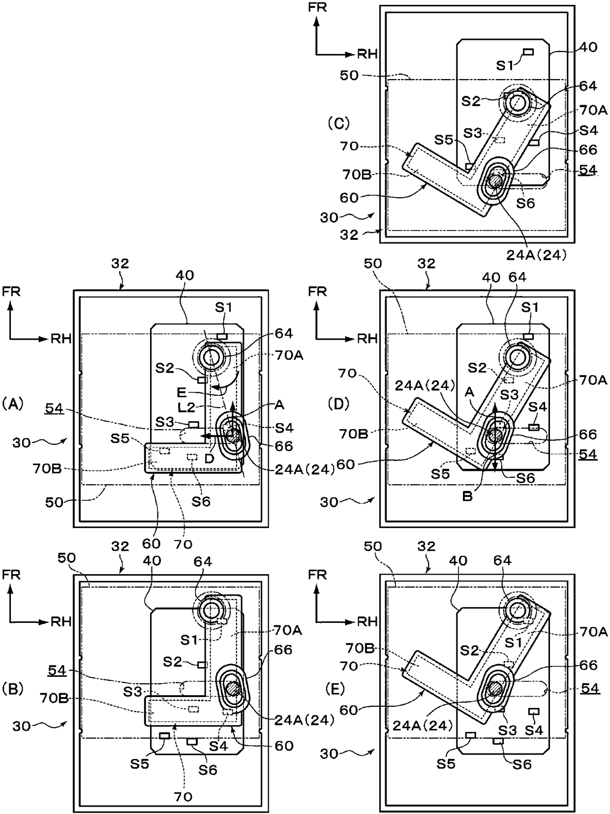
[0103] Below, according to Figure 1 to Figure 5 The shift lever device 10 according to the first embodiment will be described. In addition, in the drawings, arrow UP, arrow FR, and arrow RH indicated as appropriate indicate the upper side, the front side, and the right side (one side in the width direction) of the shift lever device 10 . In addition, the directions of up and down, front and rear, and left and right used in the following description mean up and down, front and rear, and left and right of the shift lever device 10 unless otherwise specified.
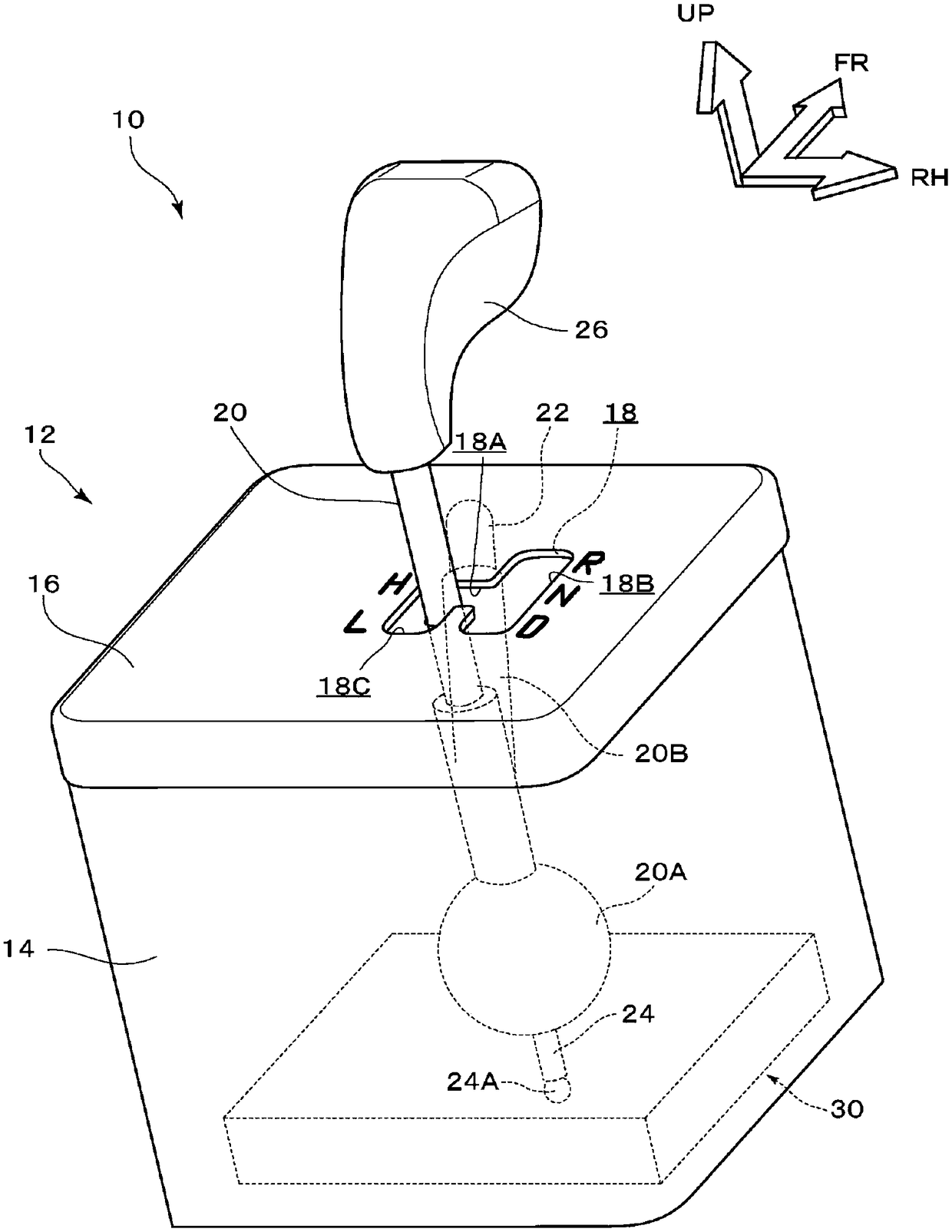
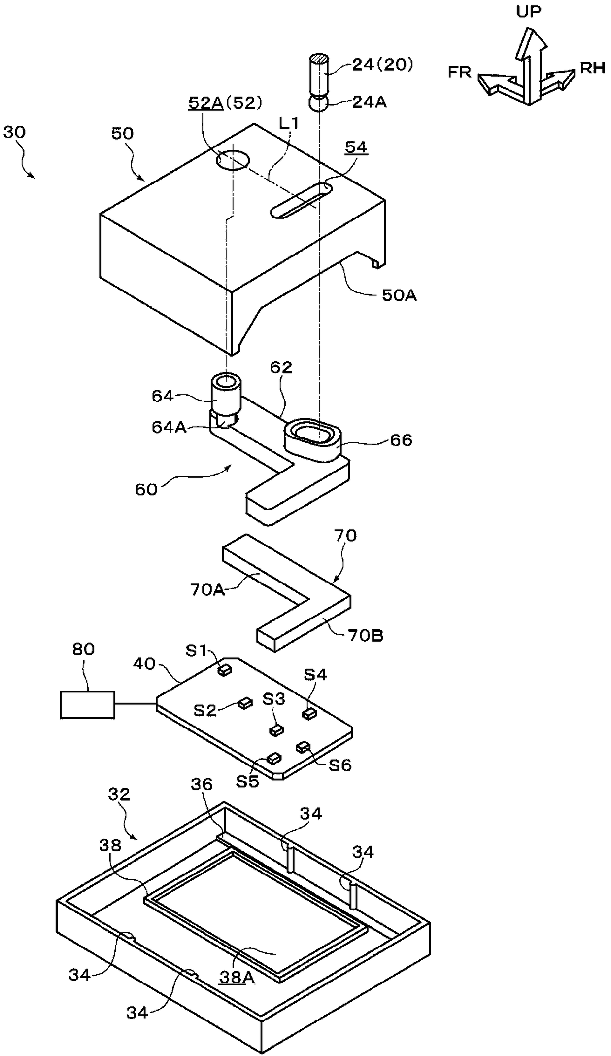
[0104] Such as figure 2 As shown, the shift lever device 10 is composed of: a housing 12 , a shift lever 20 , and a gear detection mechanism 30 . Next, each configuration of the shift lever device 10 will be described.
[0105] (about the case)
[0106] The housing 12 constitutes a frame of the shift lever device 10 and is formed in a substantially rectangular parallelepiped box shape, and is installed on a center co...
no. 2 approach >
[0151] Below, according to Figure 6 ~ Figure 9 The shift lever device 100 of the second embodiment will be described. The second embodiment has the same configuration as the shift lever device 10 of the first embodiment except for the shift position detection mechanism 130 in the shift lever device 100 . Next, the structure of the gear detection mechanism 130 will be described. In addition, in the following description, the same code|symbol is attached|subjected to the component comprised similarly to the shift lever apparatus 10 of 1st Embodiment. In addition, in the following description, unless otherwise specified, the state in which the shift lever 20 is arrange|positioned at the "H" range is demonstrated.
[0152] Such as Image 6 and Figure 7 As shown, the gear detection mechanism 130 is composed of: a housing 132 , a base plate 140 , a slider 150 , a bracket 160 , a magnet 170 as a “detected object”, and a connecting rod 190 .
[0153]The casing 132 has the same ...
PUM
Abstract
The present invention provides a shift lever device to improve the degree of freedom in the arrangement of a detecting body. The shift lever device (10) includes: a shift lever (20) configured to be operable in a shifting direction and a selection direction, and selecting a gear by operation; a detected body (magnet (70)) which is operated and moves with the shift lever (20) in a linked manner; aplurality of detecting bodies (a first sensor (S1) to a sixth sensor (S6)) disposed opposite to the detected body (magnet (70)), and outputting a detection signal corresponding to the moving positionof the detected body; a control unit (80) detecting the gear position of the shift lever (20) according to the output combination of the plurality of detection bodies; a gear position detecting mechanism (30), shifting according to the shift lever (20) in one direction of the shifting direction and selection direction to rotate the detected body (magnet (70)) by taking a relative direction of thedetected body (magnet (70)) and the detecting bodies (a first sensor (S1) to a sixth sensor (S6)) as an axial direction.
Description
technical field [0001] The present invention relates to shift lever devices. Background technique [0002] In the shift lever device, the position of the shift lever is detected using a plurality of sensors (detection bodies) and magnets (detection objects). For example, a shift lever device described in Patent Document 1 below includes a pair of magnets, and one of the pair of magnets is rotated according to an operation of the shift lever in a shift direction or a selection direction. Therefore, a mechanism for separately rotating the pair of magnets is required, and there is room for improvement in terms of a complex structure. [0003] On the other hand, in the shift lever devices of Patent Documents 2 and 3 described below, the position of the shift lever is detected by the magnet sliding relative to the sensor in accordance with the operation of the shift lever. [0004] patent documents [0005] Patent Document 1: Japanese Patent No. 4068393 [0006] Patent Docume...
Claims
Application Information
Patent Timeline
Application Date:The date an application was filed.
Publication Date:The date a patent or application was officially published.
First Publication Date:The earliest publication date of a patent with the same application number.
Issue Date:Publication date of the patent grant document.
PCT Entry Date:The Entry date of PCT National Phase.
Estimated Expiry Date:The statutory expiry date of a patent right according to the Patent Law, and it is the longest term of protection that the patent right can achieve without the termination of the patent right due to other reasons(Term extension factor has been taken into account ).
Invalid Date:Actual expiry date is based on effective date or publication date of legal transaction data of invalid patent.

