Air inflation device

An inflatable device and air valve technology, applied in the direction of valve device, valve for inflation, valve operation/release device, etc., can solve the problems of air leakage and inconvenient operation of the inflatable device, and achieve continuous deflation and operation process. simple effect

Pending Publication Date: 2018-05-29
SHENZHEN JIANYING TECH CO LTD
View PDF6 Cites 2 Cited by
  • Summary
  • Abstract
  • Description
  • Claims
  • Application Information

AI Technical Summary

Problems solved by technology

[0004] The object of the present invention is to provide an inflatable device, which aims to solve the inconvenient operation of the inflatable device in the prior art when it is deflated, and it is necessary to use fingers or other auxiliary tools to continuously push the sealing gaskets at the air inlet and the air outlet. Technical problems that allow the air inside the product to escape completely

Method used


Image

  • Air inflation device
  • Air inflation device
  • Air inflation device

Examples


Embodiment Construction

[0037] Embodiments of the present invention are described in detail below, examples of which are shown in the drawings, wherein the same or similar reference numerals designate the same or similar elements or elements having the same or similar functions throughout. The embodiments described below by referring to the figures are exemplary and are intended to explain the present invention and should not be construed as limiting the present invention.

[0038] In order to make the object, technical solution and advantages of the present invention clearer, the present invention will be further described in detail below in conjunction with the accompanying drawings and embodiments.

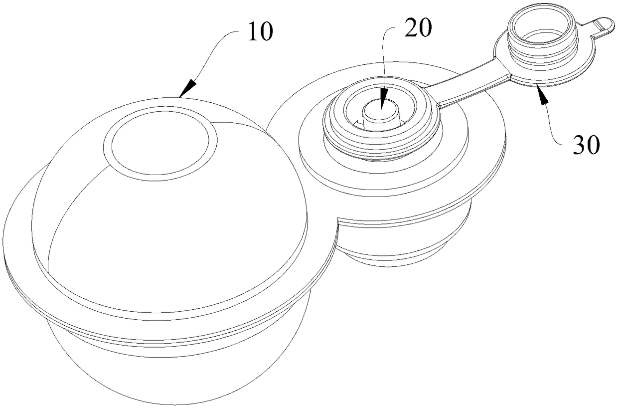
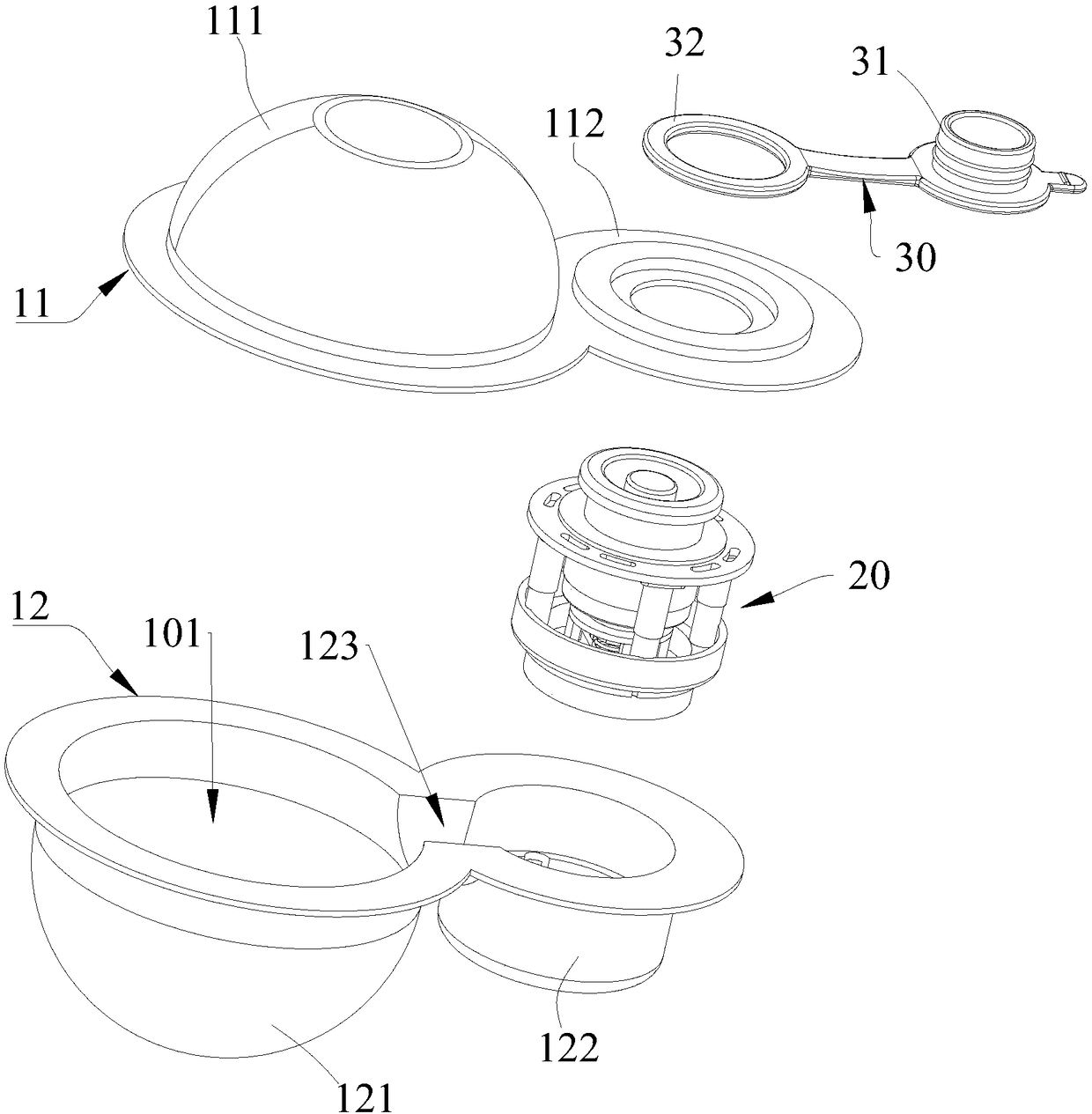
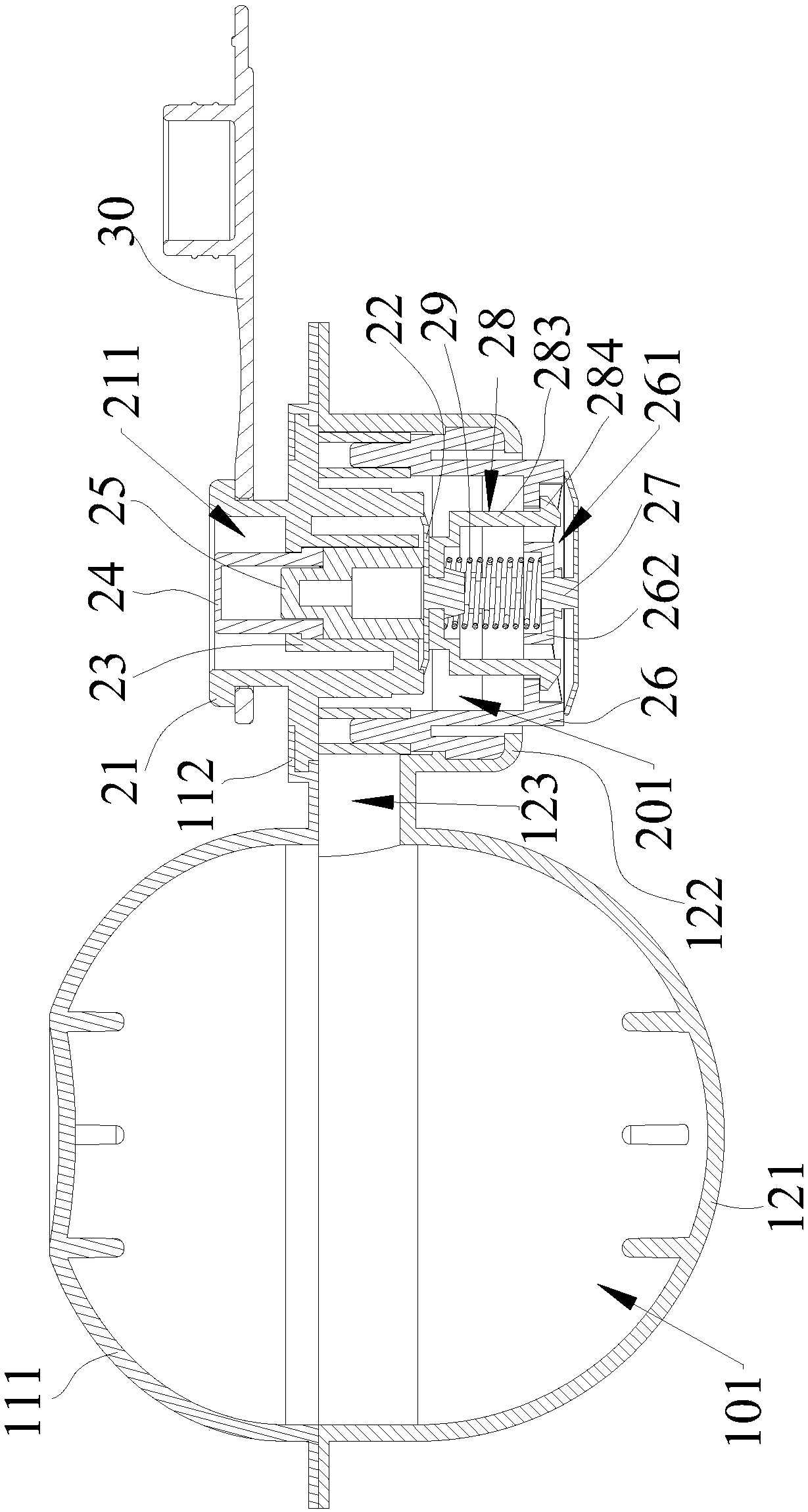
[0039] refer to Figure 1 to Figure 3 As shown, the inflatable device provided by the embodiment of the present invention includes an airbag 10 and an air valve 20 . The airbag 10 is hollow inside and communicates with the valve cavity 201 of the air valve 20 . The gas valve 20 includes an upper valv...


PUM


Abstract

The invention is applicable to the technical field of air inflation devices and provides an air inflation device convenient to operate during deflation. The air inflation device provided by the invention comprises an air bag and an air valve. The interior of the air bag is hollow and communicates with a valve cavity of the air valve. The air valve comprises an upper valve body, an upper valve pad,a key, a rotary disk, a lower valve body, a lower valve pad, a push part and a reset spring. The upper valve body is provided with an air inlet. The upper valve pad is arranged at the bottom of the upper valve body and used for sealing the air inlet and can be opened unidirectionally. The lower valve body is provided with an air outlet. The lower valve pad is arranged at the bottom of the lower valve body and used for sealing the air outlet and can be opened unidirectionally. The key and the rotary disk are arranged in the upper valve body in the axial direction. The push part is arranged between the upper valve pad and the lower valve pad. The reset spring is arranged between the push part and the lower valve body in an abutting mode. When the key is pressed to a preset travel, the rotary disk moves axially to push the upper valve pad open and push the lower valve pad open through the push part and meanwhile rotates circumferentially to get stuck on the upper valve body, and then continuous deflation is achieved.

Description

technical field [0001] The invention belongs to the technical field of inflators, in particular to an inflator with simple deflation operation. Background technique [0002] With more and more opportunities for people to go out to work or travel, many inflatable products, such as inflatable toys, swimming rings, inflatable pillows, inflatable mattresses, etc., are used more and more widely, and the air in the products will be emptied when not in use. It is convenient to carry and store in order to reduce the volume. When it needs to be used, it is necessary to inflate the product. The most primitive way of inflating is to blow air through the mouth of the person against the air inlet nozzle on the product, but this is time-consuming and laborious, and it is also unhygienic. If you use tools such as pumps to inflate, it will save time and effort, but it is more troublesome to carry tools such as pumps. [0003] In order to be able to inflate conveniently, there are currentl...

Claims


Application Information

Patent Timeline
Patent Type & Authority Applications(China)
IPC IPC(8): F16K24/06
CPCF16K24/06F16K15/202F16K15/205F16K31/524F16K15/1825
Inventor 张舰
Owner SHENZHEN JIANYING TECH CO LTD
Why Eureka
Try Eureka