
Novel high-performance glue applicator

A gluing roller, high-performance technology, applied in the direction of coating, liquid coating device on the surface, etc., can solve problems such as bearing lockup, poor sealing of gluing mechanism, glue leakage to the workbench, etc., and achieve reduction The possibility of glue leakage, reducing the amount of glue storage, and better leak-proof effect

Inactive Publication Date: 2018-06-01
李静
View PDF0 Cites 1 Cited by
  • Summary
  • Abstract
  • Description
  • Claims
  • Application Information

AI Technical Summary

Problems solved by technology

[0002] At present, when the gluing devices on the market are working, the high-temperature glue in the glue supply box is driven by the rotation of the gluing shaft to lift the glue, so that the glue is evenly covered on the surface of the working part of the gluing shaft to realize the gluing function. The rubber shaft has been doing relative rotary motion in a high temperature environment, which is likely to cause poor sealing of the glue applicator mechanism. On the one hand, it is easy to cause glue to flow into the bearing, and cause the bearing to lock after the glue cools and solidifies, resulting in the failure of the glue applicator of the edge seal. Normal work, on the other hand, it is very easy for glue to leak onto the workbench, which seriously affects the cleanliness of the workbench and the working environment, and is also a waste of glue

Method used


Image

  • Novel high-performance glue applicator

Examples


Embodiment 1

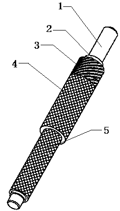
[0012] This embodiment provides a new high-performance gluing roller, which is characterized in that: the high-performance new gluing roller includes a bearing connection part (1), a positioning step surface (2), a spiral expansion plug (3), a supply Rubber cavity (4), glue roller shaft (6);

[0013] Among them: one end of the glue roller shaft (6) is movably connected to install the glue supply chamber (4), and the other end of the glue supply chamber (4) is provided with a spiral expansion plug (3) with the same inner diameter as the glue supply chamber (4), and a bolt expansion plug ( 3) The outer end is fixedly connected to the bearing connection part (1), and the connection part is provided with a positioning step surface (2).

[0014] The bearing connection part (1) is externally connected with a bearing or a driving device.


PUM


Abstract

The invention provides a novel high-performance glue applicator. The novel high-performance glue applicator is characterized by comprising a bearing connecting part, a positioning step surface, a screw telescopic plug, a glue supply cavity and a glue application roller shaft, wherein the glue supply cavity is movably connected with one end of the glue application roller shaft; the screw telescopicplug with the inner diameter the same as that of the glue supply cavity is arranged at the other end of the glue supply cavity; the bearing connecting part is fixedly connected with the outer end ofthe screw telescopic plug; the positioning step surface is mounted at the joint; the bearing connecting part is externally connected with a bearing or a drive device. The novel high-performance glue applicator is simple in structure and adopts an ingenious principle, a spiral lifting groove is formed in the position, corresponding to a long and thin gap, of the glue application shaft, and therefore, the spiral lifting groove initiatively lifts glue entering the long and thin gap from bottom to top in a rotating process of the glue application shaft and enables the glue to enter the glue supplybox; compared with the passive type sealing leakage-proof mode in the prior art, the storage amount of the glue in the long and thin gap is reduced to the great degree, the probability of glue leakage is reduced from the source, and the leakage-proof effect of the glue applicator is better.

Description

technical field [0001] The invention relates to a mechanical processing device, in particular to a gluing device, and particularly provides a high-performance new gluing roller. Background technique [0002] At present, when the gluing devices on the market are working, the high-temperature glue in the glue supply box is driven by the rotation of the gluing shaft to lift the glue, so that the glue is evenly covered on the surface of the working part of the gluing shaft to realize the gluing function. The rubber shaft has been doing relative rotary motion in a high temperature environment, which is likely to cause poor sealing of the glue applicator mechanism. On the one hand, it is easy to cause glue to flow into the bearing, and cause the bearing to lock after the glue cools and solidifies, resulting in the failure of the glue applicator of the edge seal. Normal work, on the other hand, it is very easy for glue to leak onto the workbench, which seriously affects the cleanli...

Claims


Application Information

Patent Timeline
Patent Type & Authority Applications(China)
IPC IPC(8): B05C1/08
CPCB05C1/0808
Inventor 李静
Owner 李静
Learn More