Laser radar mounting bracket and sensing system

A technology of laser radar and mounting bracket, which is applied in the field of driverless car sensing, and can solve problems such as inconvenient installation, large quality, and large volume

Inactive Publication Date: 2018-06-01
TIANJIN TRINOVA AUTOMOTIVE TECH CO LTD
View PDF4 Cites 8 Cited by
  • Summary
  • Abstract
  • Description
  • Claims
  • Application Information

AI Technical Summary

Problems solved by technology

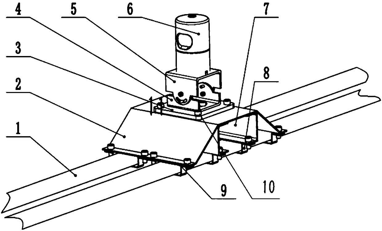
[0006] The purpose of the present invention is to provide a laser radar mounting bracket and a sensing system to alleviate the problems in the prior art that the laser radar mounting bracket is large in size, heavy in weight, complex in structure, and inconvenient to install

Method used


Image

  • Laser radar mounting bracket and sensing system
  • Laser radar mounting bracket and sensing system
  • Laser radar mounting bracket and sensing system

Examples


Embodiment Construction

[0035] The technical solutions of the present invention will be clearly and completely described below in conjunction with the accompanying drawings. Apparently, the described embodiments are some of the embodiments of the present invention, but not all of them. Based on the embodiments of the present invention, all other embodiments obtained by persons of ordinary skill in the art without making creative efforts belong to the protection scope of the present invention.

[0036] In the description of the present invention, it should be noted that the terms "center", "upper", "lower", "left", "right", "vertical", "horizontal", "inner", "outer" etc. The indicated orientation or positional relationship is based on the orientation or positional relationship shown in the drawings, and is only for the convenience of describing the present invention and simplifying the description, rather than indicating or implying that the referred device or element must have a specific orientation, ...


PUM


Abstract

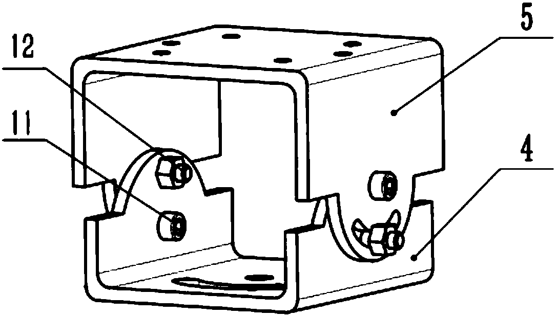
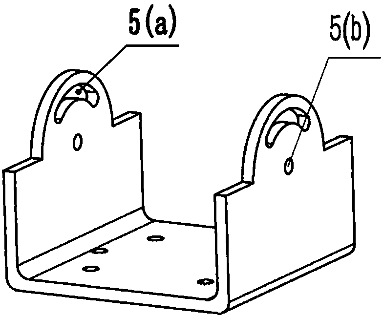
The invention provides a laser radar mounting bracket and a sensing system, which relate to the technical field of unmanned vehicle sensing. The laser radar mounting bracket is suitable for being mounted on a carrier, and comprises a general support frame, a lower adjustment support, an upper adjustment support and a laser radar, wherein the general support frame can be mounted on the carrier; thelower adjustment support is mounted on the top part of the general support frame; the lower adjustment support can rotate around a vertical axis relative to the general support frame; the upper adjustment support is mounted at the upper part of the lower adjustment support, and the two can rotate relatively around a horizontal axis; and the laser radar is mounted at the top part of the upper adjustment support. A sensing system comprises the laser radar mounting bracket. The invention aims at providing a laser radar mounting bracket and a sensing system, so as to alleviate the problems of large volume, large mass, complex structure and inconvenient mounting of the laser radar mounting bracket in the prior art.

Description

technical field [0001] The invention relates to the technical field of unmanned vehicle sensing, in particular to a laser radar mounting bracket and a sensing system. Background technique [0002] At present, driverless cars mostly use lidar as the sensor for environmental perception, and use the trunk to connect the luggage rack on the car as the fixed base of the lidar. Facilitate adjustment during installation. [0003] The existing lidar mounting bracket is too bulky and heavy. During the installation process, a variety of auxiliary tools are required to complete the installation, and the installation of a large mass bracket on the roof will affect the dynamic performance of the vehicle, increasing the Energy consumption also reduces the streamlined shape of the vehicle and affects its aesthetics; at the same time, placing an excessively large mounting bracket on the roof will increase the height of the vehicle's center of mass and reduce the driving safety performance ...

Claims


Application Information

Patent Timeline
Patent Type & Authority Applications(China)
IPC IPC(8): G01S7/481G01S17/88
Inventor 景东印赵洵刘祺刘镔豪李亮
Owner TIANJIN TRINOVA AUTOMOTIVE TECH CO LTD
Why Eureka
Try Eureka