An uplink joint receiving method and base station
A joint reception and base station technology, applied in wireless communication, electrical components, network planning, etc., can solve problems such as high cost, reduce packet loss and word swallowing, improve uplink transmission efficiency, improve transmission reliability and call success rate effect
- Summary
- Abstract
- Description
- Claims
- Application Information
AI Technical Summary
Problems solved by technology
Method used
Image

Examples
Embodiment 1
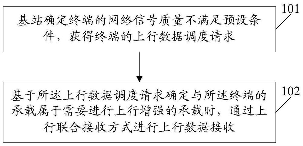
[0044] An embodiment of the present invention provides an uplink joint receiving method. image 3 It is a schematic flowchart of an uplink joint receiving method in Embodiment 1 of the present invention; image 3 As shown, the method includes:
[0045] Step 101: the base station determines that the network signal quality of the terminal does not meet a preset condition, and obtains an uplink data scheduling request of the terminal.
[0046] Step 102: When it is determined based on the uplink data scheduling request that the bearer with the terminal belongs to the bearer that needs uplink enhancement, perform uplink data reception in an uplink joint reception manner.
[0047] In this embodiment, the uplink joint reception method is applied to a base station, and the terminal is within the network coverage of the base station; the base station may be a serving base station of the terminal.
[0048]In this embodiment, after the base station establishes a bearer with the termina...
Embodiment 2
[0057] The embodiment of the present invention also provides an uplink joint receiving method. Figure 4 It is a schematic flow chart of the uplink joint receiving method in Embodiment 2 of the present invention; Figure 4 As shown, the method includes:
[0058] Step 201: After the base station establishes a bearer with the terminal, or when the base station performs uplink / downlink scheduling on the terminal for the first time based on the bearer, the base station sends an A2 measurement control instruction to the terminal, and the A2 measurement control instruction corresponds to The measurement control condition is that the RSRP of the terminal under the serving cell is lower than the first threshold;
[0059] Step 202: When the terminal reports an A2 measurement report to the base station based on the received A2 measurement control instruction, the base station sends a CoMP A3 measurement control instruction to the terminal, and the measurement control instruction corres...
Embodiment 3
[0068] Based on the first embodiment, this embodiment further describes in detail a manner of judging whether the bearer where the current data is retrieved belongs to the bearer that needs uplink enhancement. Specifically, in order to improve the efficiency of uplink transmission with weak coverage of VoLTE services, the bearer that requires enhanced uplink coverage is the QoS class identifier (QCI, QoS ClassIdentifier) 1 bearer for transmitting VoLTE service packets. The base station to which the serving cell belongs can start the solution in Embodiment 1 of the present invention when the QCI 1 bearer is established. For a terminal that has established a QCI 1 bearer, the base station can determine the bearer to which the uplink scheduling belongs according to the number of transmitted bits when the terminal applies for uplink scheduling. For example, when the number of transmitted bits for which the terminal applies for uplink scheduling is about 562 bits (bits) (the numb...
PUM
 Abstract
Description
Claims
Application Information
 - R&D
- Intellectual Property
- Life Sciences
- Materials
- Tech Scout
- Unparalleled Data Quality
- Higher Quality Content
- 60% Fewer Hallucinations
Browse by: Latest US Patents, China's latest patents, Technical Efficacy Thesaurus, Application Domain, Technology Topic, Popular Technical Reports.
© 2025 PatSnap. All rights reserved.Legal|Privacy policy|Modern Slavery Act Transparency Statement|Sitemap|About US| Contact US: help@patsnap.com